
ZETA 40/60/100
Brugsanvisning
Instruction manual
Betriebsanleitung
Manuel d’instruction
Bruksanvisning
Käyttöohje
Manuale d’istruzione
Gebruikershandleiding
Руководство по эксплуатации
Valid from 2013 week 45 50114756 L

EC DECLARATION OF CONFORMITY
MIGATRONIC A/S
Aggersundvej 33
9690 Fjerritslev
Denmark
hereby declare that our machine as stated below
Type: ZETA 40/60
As of Week 02 2013
Type: ZETA 100
As of Week 02 2013
conforms to directives 2006/95/EC
2004/108/EC
2011/65/EU
European Standards: EN/IEC60974-1
EN/IEC60974-10 (Class A)
Issued in Fjerritslev 7 January 2013
Anders Hjarnø Jørgensen
CEO
EC DECLAR
A
TION OF CONFORMITY
MIGATRONIC A/S
Aggersundvej 33
9690 Fjerritslev
Denmark
hereby declare that our plasma cutting torches
Type: PT 100
As of Week 02 2013
conforms to directives 2006/95/EC
2004/108/EC
2011/65/EU
European Standards: EN/IEC60974-7
Issued in Fjerritslev 7 January 2013
Anders Hjarnø Jørgensen
CEO

DK – INDHOLDSFORTEGNELSE - Advarsel / Elektromagnetisk støjudstråling...................................................................................... 5
- Maskinprogram / Hvad er plasmaskæring....................................................................................... 6
- Ibrugtagning ..................................................................................................................................... 6
- Betjeningsvejledning ........................................................................................................................ 8
- Vedligeholdelse .............................................................................................................................. 10
- Tekniske data ................................................................................................................................. 11
- Garantibestemmelser .................................................................................................................... 12
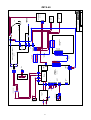
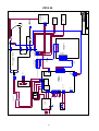
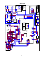
- Kredsløbsdiagrammer ............................................................................................................ 77 - 79
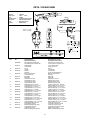
- Reservedelsliste
GB – CONTENTS - Warning / Electromagnetic emissions ........................................................................................... 13
- Machine programme / What is plasma cutting .............................................................................. 14
- Initial instructions ............................................................................................................................ 14
- Control unit ..................................................................................................................................... 16
- Maintenance .................................................................................................................................. 18
- Technical data ................................................................................................................................ 19
Warranty regulations ...................................................................................................................... 20
- Circuit diagrams ...................................................................................................................... 77 - 79
- Spare parts list
D – INHALTSVERZEICHNIS - Warnung / Elektromagnetische Störungen.................................................................................... 21
- Produktübersicht / Was ist Plasmaschneiden ............................................................................... 22
- Anschluß und Inbetriebnahme ....................................................................................................... 22
- Kontrolleinheit ................................................................................................................................ 24
- Wartung ......................................................................................................................................... 26
- Technische Daten .......................................................................................................................... 27
- Garantiebedingungen .................................................................................................................... 28
- Koppeldiagramme ................................................................................................................... 77 - 79
- Ersatzteilliste
F – TABLE DES MATIERES - Avertissement / Emissions électromagnétiques ............................................................................ 29
- Programme de la machine / Définition de la découpe au plasma ................................................ 30
- Instructions préalables ................................................................................................................... 30
- Unité de commande ....................................................................................................................... 32
- Maintenance .................................................................................................................................. 34
- Caractéristiques techniques .......................................................................................................... 35
Garantie ......................................................................................................................................... 36
- Schémas de connexion .......................................................................................................... 77 - 79
- Liste des pièces de rechange
SE – INNEHÅLLSFÖRTECKNING - Varning / Elektromagnetisk störfält ................................................................................................ 37
- Maskinprogram / Vad är plasmaskärning ...................................................................................... 38
- Igångsättning ................................................................................................................................. 38
- Funktionsvägledning ...................................................................................................................... 40
- Underhåll ........................................................................................................................................ 42
- Teknisk data ................................................................................................................................... 43
- Garantibestämmelser .................................................................................................................... 44
- Kretsloppsdiagram .................................................................................................................. 77 - 79
- Reservdelslista
FI – SISÄLLYSLUETTELO - Varoitus / Sähkömagneettiset häiriöt ............................................................................................. 45
- Tuoteohjelma / Mitä plasmaleikkaus on ........................................................................................ 46
- Käyttöönotto ................................................................................................................................... 46
- Ohjausyksikkö ................................................................................................................................ 48
- Huolto ............................................................................................................................................. 50
- Tekniset tiedot ................................................................................................................................ 51
- Takuuehdot .................................................................................................................................... 52
- Kytkentäkaavio ........................................................................................................................ 77 - 79
- Varaosaluettelo
I – INDICE - Attenzione / Emissioni elettromagnetiche...................................................................................... 53
- Gamma / Cos’e’ il taglio plasma? .................................................................................................. 54
- Istruzioni iniziali .............................................................................................................................. 54
- Pannello di controllo ....................................................................................................................... 56
- Manutenzione ................................................................................................................................ 58
- Dati tecnici ...................................................................................................................................... 59
- Condizioni di garanzia ................................................................................................................... 60
- Schema elettrico ..................................................................................................................... 77 - 79
- Lista parti di ricambio
NL – INHOUD - Waarschuwing / Elektromagnetische emissie ............................................................................... 61
- Machineprogramma / Wat is plasmasnijden ................................................................................. 62
- Aan de slag .................................................................................................................................... 62
- Besturingsunit ................................................................................................................................ 64
- Onderhoud ..................................................................................................................................... 66
- Technische gegevens .................................................................................................................... 67
- Garantievoorwaarden .................................................................................................................... 68
- Elektrisch schema ................................................................................................................... 77 - 79
- onderdelenlijst
RU – СОДЕРЖАНИЕ - Предупреждения / Электромагнитные излучения .................................................................... 69
- Программа поставки / Что такое плазменная резка ................................................................. 70
- Начало работы ............................................................................................................................. 70
- Блок управления .......................................................................................................................... 72
-
Техническое обслуживание ........................................................................................................ 74
- Технические данные .................................................................................................................... 75
- Условия гарантии ......................................................................................................................... 76
- Схемы цепи ........................................................................................................................... 77 - 79
- Список запасных деталей


5
DANSK
Elektromagnetisk støjudstråling
Dette svejseudstyr, beregnet for professionel anvendelse, over-
holder kravene i den europæiske standard EN/IEC60974-10
(Class A). Standarden har til formål at sikre, at svejseudstyr ikke for-
styrrer eller bliver forstyrret af andet elektrisk udstyr som følge af
elektromagnetisk støjudstråling. Da også lysbuen udsender støj,
forudsætter anvendelse uden forstyrrelser, at der tages forholds-
regler ved installation og anvendelse. Brugeren skal sikre, at
andet elektrisk udstyr i området ikke forstyrres.
Følgende skal tages i betragtning i det omgivne område:
1. Netkabler og signalkabler i svejseområdet, som er tilsluttet
andre elektriske apparater.
2. Radio- og fjernsynssendere og modtagere.
3. Computere og elektroniske styresystemer.
4. Sikkerhedskritisk udstyr, f.eks. overvågning og processtyring.
5. Brugere af pacemakere og høreapparater.
6. Udstyr som anvendes til kalibrering og måling.
7. Tidspunkt på dagen hvor svejsning og andre aktiviteter,
afhængig af elektrisk udstyr, foregår.
8. Bygningers struktur og anvendelse.
Hvis svejseudstyret anvendes i boligområder kan det være nød-
vendigt at tage særlige forholdsregler (f.eks. information om midler-
tidigt svejsearbejde).
Metoder til minimering af forstyrrelser:
1. Undgå anvendelse af udstyr, som kan blive forstyrret.
2. Anvend korte svejsekabler.
3. Læg plus- og minuskabel tæt på hinanden.
4. Placer svejsekablerne på gulvniveau.
5. Fjern signalkabler i svejseområdet fra netkabler.
6. Beskyt signalkabler i svejseområdet f.eks. med skærmning.
7. Benyt isoleret netforsyning til følsomme apparater.
8. Overvej skærmning af den komplette svejseinstallation.
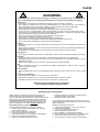
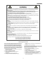
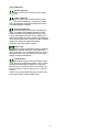
ADVARSEL
Plasmaskæring kan ved forkert brug være farlig for såvel bruger som omgivelser. Derfor må udstyret kun an-
vendes under iagttagelse af relevante sikkerhedsforskrifter. Især skal man være opmærksom på følgende:
Elektrisk stød
- Skæreudstyret skal installeres forskriftsmæssigt. Maskinen skal jordforbindes via netkablet.
- Det er farligt at få elektrisk stød. Det kan give helbredsproblemer og i værste fald slå ihjel. Ved anvendelse af
plasmaskæreudstyr skal man være særlig opmærksom, fordi der arbejdes med meget høje spændinger.
- Sørg for regelmæssig kontrol af maskinens sikkerhedstilstand.
- Beskadiges kabler og isoleringer, skal arbejdet omgående afbrydes og reparation foretages.
- Kontrol, reparation og vedligeholdelse af udstyret skal foretages af en person med den fornødne faglige indsigt.
- Undgå berøring af spændingsførende dele i skærekredsen (skærebrænder og stelklemme) med bare hænder.
Brug aldrig defekte eller fugtige svejsehandsker og hold tøjet tørt.
- Isolér Dem selv fra jorden og svejseemnet (brug f.eks fodtøj med gummisål).
- Brug en sikker arbejdsstilling (undgå f.eks. fare for fald).
- Følg reglerne for "Svejsning under særlige arbejdsforhold" (Arbejdstilsynet).
- Afbryd maskinen før skærebrænderen adskilles ved udskiftning af elektrode og anden service.
- Brug kun specificeret skærebrænder og reservedele (se reservedelslisten)
Skærelys
- Beskyt øjnene idet selv en kortvarig påvirkning kan give varige skader på synet. Brug svejsehjelm med foreskrevet
filtertæthed.
- Beskyt kroppen mod lyset fra lysbuen idet huden kan tager skade af stråling. Brug beskyttende beklædning der
dækker alle dele af kroppen.
- Arbejdsstedet bør om muligt afskærmes, og andre personer i området advares mod lyset fra lysbuen.
Røg og gasser
- Røg og gasser, som dannes ved skæring, er meget farlige at indånde. Sørg for tilstrækkelig udsugning og ventilation.
Brandfare
- Stråling og gnister fra lysbuen kan forårsage brand. Letantændelige genstande fjernes fra svejsepladsen.
- Arbejdstøjet skal også være sikret mod gnister og sprøjt fra lysbuen (Brug evt. brandsikkert forklæde og pas på
åbenstående lommer).
- Særlige regler er gældende for rum med brand- og eksplosionsfare. Følg disse forskrifter.
Støj
- Lysbuen frembringer akustisk støj, og støjniveauet er betinget af skæreopgaven. Støjen har ofte et niveau der
kræver at høreværn anvendes.
Farlige områder
- Særlig forsigtighed skal udvises, når skærearbejdet foregår i lukkede rum, eller i højder hvor der er fare for at falde
ned.
Placering af skæreudstyret
- Placer skæreudstyret således at der ikke er risiko for, at det vælter.
- Særlige regler er gældende for rum med brand- og eksplosionsfare. Følg disse forskrifter.
Anvendelse af maskinen til andre formål end det, den er beregnet til er på eget ansvar.
Gennemlæs denne instruktionsbog omhyggeligt,
inden udstyret installeres og tages i brug!

6
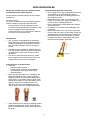
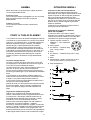
MASKINPROGRAM
ZETA 40/60/100 er en luftkølet plasmaskæremaskine.
Svejseslanger og kabler
Til maskinerne kan MIGATRONIC fra sit produkt-
program levere returstrømkabler, sliddele mm.
Transportvogn (ekstraudstyr)
Maskinerne kan leveres med transportvogn.
HVAD ER PLASMASKÆRING
Plasmafysik
Plasmalysbuen er en meget koncentreret lysbue, der
opstår ved, at lysbuen bliver mekanisk koncentreret og
indsnævret igennem et lille dysehul. Denne ind-
snævring giver meget høje temperaturer (over
15000°C) og en meget høj hastighed. Den høje tem-
peratur gør materialet flydende, og materialet presses
væk af den kinetiske energi i lysbuen.
En ideel plasmagas er molekylær, har høj varme-
ledningsevne, er let at ionisere og har høj molekyle-
vægt. Trykluft er velegnet som plasmagas, dog skal
brænderen have en særlig udformning, idet der er ilt i
trykluften.
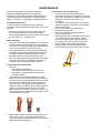
Plasmabrænderen
En plasmabrænder ligner en TIG-svejsebrænder, hvor
der er tilføjet en dyse for at lave en mekanisk ind-
snøring af lysbuen.
Elektroden består af kobber, hvori der er indpresset en
hafniumstift. Dysen er udført i kobber.
Der er kun en tryklufttilledning til pistolen, hvor gassen
deles til plasmagas og kølegas. For at lysbuen kan
tændes, udledes en HF-gnist mellem elektrode og
dyse. Derved ioniseres plasmagassen, og pilotlysbuen
tændes. Af sikkerhedshensyn, samt for at undgå op-
varmning og slitage, er pilotlysbuetiden begrænset til
max. 3 sek.
Når brænderen placeres tæt på skæreemnet, vil lys-
buen blive overført til emnet, pilotlysbuen slukkes og
skæreprocessen starter.
Skæring i metalnet og gittre
Det er nødvendigt at fremføre brænderen konstant
fremad, når lysbuen er overført til skæreemnet, og
skæreprocessen er i gang. Ellers slukkes lysbuen. Det
samme sker, hvis brænderen føres væk fra svejse-
emnet.
Hvis det er nødvendigt at skære i metalnet, gitre eller
andre afbrudte materialer, er det nødvendigt at an-
vende ”gitter” funktionen. I denne skæreproces vil ma-
skinen altid have lysbuen tændt. Desværre vil
brænder- og sliddele hurtigere blive brugt, og skære-
processen vil nedsættes i hastighed.
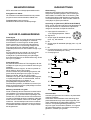
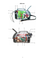
IBRUGTAGNING
Nettilslutning
Maskinen skal tilsluttes den korrekte netforsyning iht.
det påsatte typeskilt. Efter montering af netstikket er
maskinen klar til brug. Netstikforbindelsen skal fore-
tages af autoriseret og kvalificeret personale. Tænd og
sluk maskinen ved hjælp af afbryderen på maskinen.
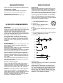
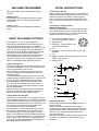
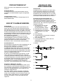
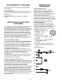
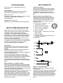
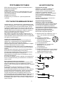
Tilslutning af fjernkontrol (ZETA 100 AUTOMAT)
ZETA 100 til automatbrug kan fjernreguleres via en
fjernkontrol eller en svejseautomat. Fjernkontrolstikket
har terminaler for følgende funktioner:
A: Input-signal for svejsestrøm, 0 –
+10V indgangsimpedans: 1Mohm
B: Signal-nul
C: Output-signal for etableret lysbue
(max. 1A), fuldt isoleret
D: NC
E: Output-signal for etableret lysbue (max. 1A), fuldt
isoleret
F: NC
G: Forsyningsspænding +24VDC. Kortslutningssikret
med PTC modstand (max. 50mA)
H: Forsynings-nul
Generatordrift
Tilslutning til generator kan medføre, at plasmaskære-
maskinen ødelægges.
Generatorer kan, i forbindelse med tilslutning til en
plasmaskæremaskine, afgive store spændingspulser
som virker ødelæggende på plasmaskæremaskinen.
Kun frekvens- og spændingsstabile generatorer af
asynkron-typen må anvendes. Defekter, som opstår
på plasmaskæremaskinen som følge af tilslutning til
generator, er ikke omfattet af garantien.

7
Tryklufttilslutning
Trykluftsslangen skal forbindes bag på strømkilden.
Trykluften skal være ren og tør for at undgå hurtigt slid
på sliddele i brænderen. For at opnå dette kan der
monteres særligt luftfilter. Trykluftsanlægget skal have
en kapacitet på min. 120 l/min ved et tryk på 6-8 bar
på ZETA 40/60 og min. 180 l/min ved et tryk på 6-
8 bar på ZETA 100. Kompressoren må ikke overstige
8 bar.
ZETA har indbygget trykreduktionsventil og et mano-
meter.
Indstilling af skæreluft
Maskinen er udstyret med en lufttryksindikator, der
stopper maskinen, hvis indløbstrykket er mindre end
3 bar.
Tænd maskinen
Tryk på ”Lufttest” tasten på betjeningspanelet (gas-
ventilen åbnes)
Fasthold tasten og juster lufttrykket til 3,5 bar. Luft-
tryksstørrelsen afhænger af materialetype, tykkelse
og strømstyrken. Overstig ikke 6 bar.
Slip tasten
Skæreprocessen
Indstil skærestrømmen i forhold til materialetype og
tykkelse.
Vælg skæremetode: normal eller ”gitter” skæring.
Hold brænderen i afstand fra personer eller objekter
og tryk på brændertasten. Pilotlysbuen tændes.
Placer brænderen tæt på skæreemnet, og lysbuen vil
blive overført. Pilotlysbuen slukkes, hvis brænderen
ikke føres tæt på skæreemnet indenfor 3 sek. efter, at
pilotlysbuen er tændt.
Start skæreprocessen fra den ene ende af skære-
emnet for at undgå, at slagger og sprøjt returnerer til
brænderen. Hvis det er nødvendigt at skære i midten
af et emne, skal brænderen hældes. Pilotlysbuen vil
tillade overførsel af lysbuen, selv på beskidte eller ma-
lede overflader.
Skærehastighed
Den korrekte skærehastighed gør det muligt at skære
materialet og fjerne det smeltede materiale fra den
modsatte side af skæreemnet.
Det smeltede materiale vil have et flow på en 10-15°
hældning på brænderakslen ved den korrekte skære-
hastighed. Det vil gøre det muligt at opnå rene skære-
hjørner uden slagger.
For langsom skærehastighed vil udvide skæreområ-
det, øge varmezonen og efterlade slagger på skære-
området.
For høj skærehastighed vil ikke skære igennem
materialet og vil returnere slagger og sprøjt.
Brænderen skal holdes lodret mod svejsemnet under
skæreprocessen.
Fordele ved plasmaskæring
Plasmaskæring giver mange fordele i forhold til auto-
genskæring. Smeltebadet er smallere med det høje
indhold af oxygen i autogenskæring, og derved er det
ikke muligt at skære i rustfrit stål. Den høje temperatur
og trykluften fjerner det smeltede materiale og efter-
lader rene skæreflader.
Plasmaskæring kan anvendes til alle elektrisk ledede
materialer.
Sliddele
Der er to sliddele i brænderen: elektrode og dyse.
Elektrodens ende af hafnium slides under skæring og
skal udskiftes, når der er 2-3mm tilbage. En udslidt
elektrode gør det vanskeligt at etablere pilotlysbuen,
og vil resultere i en ustabil lysbue og reducere skære-
kvaliteten.
Dysen skal holdes fri af skæresprøjt, da åbningen
øges og gøres skæv. Derved reduceres skærekvalite-
ten.
Levetiden er variabel og afhængig af skæreopgaver.
BEMÆRK!
Det er vigtigt at kontrollere flowet ved hjælp
af plasmagastesteren.
Flowet SKAL ligge mellem de to streger på
gastesteren.
Ligger flowet udenfor, resulterer det i enten
dårlig skærekvalitet eller kort levetid på slid-
delene.

8
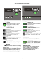
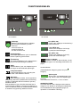
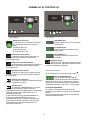
BETJENINGSVEJLEDNING
ZETA 40/60 ZETA 100
Drejeknap
Maskinen er forsynet med en drejeknap,
som anvendes til indstilling af skære-
strømmen.
20-45A for ZETA 40,
20-60A for ZETA 60,
20-100A for ZETA 100.
Plasmalysbue
Plasmalysbueindikatoren lyser af sikkerheds-
hensyn, hvis der er spænding på brænderen.
Overophedning
Overophedningsindikatoren lyser, skære-
processen er blevet afbrudt på grund af over-
ophedning af maskinen.
Netfejl
Netfejlsindikatoren lyser, når netspændingen
er mere end 15% lavere end den beregnede
spænding.
Manglende lufttryk
Lufttryksfejlindikatoren lyser, når lufttrykket
falder til under 3 bar. Maskinen stopper.
Brænderfejl
Brænderindikatoren blinker, når der opstår en
kortslutning i brænderen (skadet brænder eller dårlig
samling af elektriske dele som elektrode, dyse etc.)
Maskinen stopper.
Brænderindikatoren lyser, når brænderhovedet ikke er
korrekt samlet. Indikatoren informerer brugeren om
risikoen for elektrisk chok, da de udsatte elektriske
dele er udsat for høj spænding. Maskinen stopper.
PLS (ZETA 100)
Teksten vises i display ved kortslutning i
plasmabrænderen
LO.P (ZETA 100)
Teksten vises i displayet ved for lavt
trykluft fra lufttilslutningen.
HI.P (ZETA 100)
Teksten vises i displayet ved for højt
trykluft fra lufttilslutningen.
Visning af fejlkoder
Indikatoren ved siden af ikonet blinker, når der
opstår andre typer fejl. Samtidigt vises fejlkode i dis-
playet.
Udvalgte fejlkoder:
(Fejlmeddelelsen fjernes ved at trykke -tasten)
Spændingsfejl
Ikonet vises, når netspændingen er for
høj. E04-01 vises, når netspændingen
er for lav.
Tilslut maskinen til 400V AC, +/-15% 50-60Hz.
ANDRE FEJLTYPER
Hvis andre fejlkode vises i display skal maskinen
slukkes og tændes for at fjerne meddelelsen.
Hvis fejlmeddelelsen vises gentagne gange, er
reparation af strømkilden nødvendig.

9
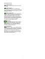
Valg af skæremetode
Normal skæring
Denne funktion bør være aktiv under normal
brug.
”Gitter”skæring
Denne funktion bør kun anvendes under
specielle forhold (f.eks. skæring i metalnet), da
levetiden på sliddele til brænderen afkortes, og skære-
hastigheden nedsættes.
Fugning (ZETA 100)
Til denne funktion anvendes en særlig dyse,
der tillader plasmabuen at blæse det smeltede
materiale væk og derved skabe en fuge. Under
fugning skal brænderen holdes i en 45° hældning i
forhold til skæreemne og brugeren skal sikre sig, at
brænderen holdes, så det smeltede materiale blæses i
den rigtige retning rent sikkerhedsmæssigt.
Lufttrykket skal være indstillet til 3,5 bar.
(ZETA 100)
Denne funktion anvendes til visning af lysbue-
spænding eller skærestrøm. Tasten holdes
nede i 3 sekunder, og “A” indikatoren slukkes, når
lysbuespændingen vises. Når tasten trykkes igen,
returnerer visningen til skærestrøm.
Lufttrykstest
Gasventilen åbnes, uden at lysbuen tændes.
Det er da muligt at kontrollere og evt. justere
på lufttryksmåleren bag på maskinen. Lufttrykket skal
være 3,5 bar for ZETA 40/60, og for ZETA 100
anbefales 4,0 bar for skæring og 3,5 bar for fugning.
Ved at trykke på lufttrykstasten på ZETA 100 vises
trykket på den komprimerede luft.

10
VEDLIGEHOLDELSE
Manglende vedligeholdelse kan medføre nedsat
driftssikkerhed og bortfald af garanti.
Der skal udføres periodisk eftersyn på ZETA skære-
maskinerne.
Periodisk eftersyn:
For at sikre en problemfri drift skal følgende eftersyn
udføres mindst en gang årligt, eller efter behov.
- Afbryd maskinen fra forsyningsnettet og vent
2 minutter inden sideskærmene afmonteres. Dette
må kun foretages af elkyndigt personale.
- Ventilatorvingerne og komponenterne i kølekana-
len renses for snavs med trykluft.
Vandudskiller
Tøm og rengør vandudskilleren på regulatoren.
Dette gøres ved at trykke på udluftningsventilen i
bunden af glaskappen når trykluften er sluttet til,
eller ved at skrue kappen helt af og rengøre for
smuds.
Urenheder i luften medfører at elektrode og dyse
irrer eller danner kortslutninger mellem elektroden
og skæredysen. Fugt i luften forhindrer start af
pilotlysbue.
Hvis der har været urenheder eller fugt i skære-
luften, rengøres enden af elektroden og den ind-
vendige side af dysen med fint sandpapir.
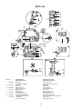
Plasmaslangen og skærehovedet
Undersøg
- skærehovedet for skader,
- plasmaslangen for skader på overtrækket
og udskift efter behov dyse, elektrode og
elektrodeisolator.
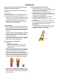
Dysen bør jævnligt rengøres for metalsprøjt ved
hjælp af en stålbørste. Der må ikke anvendes
skarpe genstande, da disse kan beskadige dyse-
hullet. Dysen er en sliddel, og det er derfor vigtigt
jævnligt at kontrollere, om den skal skiftes. Der er
risiko for nedsmeltning i skærehovedet, hvis
udskiftning ikke sker i tide. Nedenstående foto
viser ny dyse til venstre og nedslidt dyse til højre.
Under skæring kan der dannes metalsprøjt mellem
elektrode og dysekappe. Dette metalsprøjt skal
fjernes ved at blæse trykluft ind, mens man banker
let på det.
Brænder/tændingsfunktion (Zeta 100)
Det er vigtigt at sikre sig, at tændingsmekanismen
er bevægelig, hver gang elektroden skiftes.
Smøring er nødvendig, hvis tændingsfunktionen
ikke fungerer korrekt.
Nedenstående foto viser, hvor smøringen skal
foregå, og hvordan det er vigtigt at skubbe op og
ned for at smøre tændingsfunktionen.
Fjern overskydende smøremiddel inden samling
af brænderhoved.
Vi anbefaler ren vaseline uden tilsætninger eller
paraffinolie.
Andre smøremidler som f.eks. toluen, xylen eller
benzen (især som spray) er ikke tilladt, da det kan
ødelægge indre dele af brænderens mekanisme.
Silicium-baserede, Lithium-baserede og Teflon-
baserede produkter er IKKE tilladte, da de kan
reagere med indvendige gummidele.

11
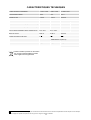
TEKNISKE DATA
Strømkilde: ZETA 40 ZETA 60 ZETA 100
Netspændin
g
(
50Hz-60Hz
)
1 x 230 V ±15% 3x400 V ±15% 3 x 400 V ±15%
Netsikring 16 A 10 A 20 A
Netstrøm, effekti
v
16,8 A 6,8 A 19,1 A
Effekt, (100%) 3,9 kVA 4,7 kVA 13,2 kVA
Effekt, max 5,3 kVA 7,4 kVA 29,9 kVA
Effekt, tom
g
an
g
< 35 W < 35 W < 35 W
Virkningsgrad 0,9 0,9 0,8
Tilladelig belastning: Skærin
g
Fugnin
g
100% (40° omgivelsestemp) 35 A / 94 V 40A / 96 V 75 A / 110 V 75 A / 130 V
60% (40° omgivelsestemp) 40 A / 96 V 50 A / 100 V 85 A / 114 V 85 A / 134 V
40% (40° omgivelsestemp) 45 A / 98 V 60 A / 104 V 100 A / 120 V -
35% (40° omgivelsestemp) - - - 100 A / 140 V
100%
(
20° om
g
ivelsestemp
)
40 A / 96 V 45 A / 98 V - -
60% (20° omgivelsestemp) 45 A / 98 V 55 A / 102 V - -
Tomgangsspænding 225 V 241 V 248 V
Strømområde 20-45 A 20-60 A 20-100 A
1
Anvendelsesklasse
S
S
S
2
Besk
y
ttelsesklasse
(
IEC 529
)
IP 23 IP 23 IP 23
Norm EN/IEC60974-1
EN/IEC60974-10 (Class A)
Dimensioner (hxbxl) (mm) 360x220x570 360x220x570 405x345x675
Væ
g
t 26k
g
27 k
g
36k
g
Kvalitetssnit 8 mm 12 mm <25 mm
Delesnit 12 mm 18 mm <35 mm
Bortskaf produktet i overensstemmelse med
gældende regler og forskrifter.
www.migatronic.com/goto/weee
1
S
Maskinen opfylder de krav der stilles under anvendelse i områder med forøget risiko for elektrisk chok
2 Maskinen må anvendes udendørs, idet den opfylder kravene til beskyttelsesklasse IP23.”

12
GARANTIBETINGELSER
Migatronic svejsemaskiner kvalitetskontrolleres
løbende i hele produktionsforløbet og afprøves som
samlede enheder gennem omhyggelig, kvalitetssikret
funktions- og sluttest.
Migatronic yder 12 måneders garanti på nye
svejsemaskiner, der ikke er registreret. Hvis nye
svejsemaskiner registreres inden for 6 uger efter
fakturering, udvides garantiperioden til 24 måneder.
Registrering skal foretages på internetadressen:
www.migatronic.com/warranty. Som bevis for
registreringen gælder registreringsbeviset, der
fremsendes pr. e-mail. Den originale faktura samt
registreringsbeviset er købers dokumentation for, at
svejsemaskinen er omfattet af en 24 måneders
garanti.
Såfremt registrering ikke foretages, er standard
garantiperioden 12 måneder for nye svejsemaskiner,
regnet fra dato for fakturering til slutkunde. Den
originale faktura er dokumentation for
garantiperioden.
Migatronic yder garanti i henhold til gældende
garantibetingelser ved at udbedre mangler eller fejl
ved svejsemaskiner, der påviseligt inden for
garantiperioden måtte skyldes materiale- eller
produktionsfejl.
Der ydes som hovedregel ikke garanti på
svejseslanger, da disse anses som sliddele; dog vil
fejl og mangler, som opstår inden for 6 uger efter
ibrugtagning og som skyldes materiale- eller
produktionsfejl, blive betragtet som
garantireklamation.
Enhver form for transport i forbindelse med en
garantireklamation er ikke omfattet af Migatronics
garantiydelse og vil derfor ske for købers regning og
risiko.
I øvrigt henvises til Migatronic gældende
garantibetingelser som er tilgængelig på:
www.migatronic.com/warranty.

13
ENGLISH
Electromagnetic emissions and the radiation of electromagnetic disturbances
This welding equipment for industrial and professional use is in
conformity with the European Standard EN/IEC60974-10 (Class A).
The purpose of this standard is to prevent the occurrence of
situations where the equipment is disturbed or is itself the source of
disturbance in other electrical equipment or appliances. The arc
radiates disturbances, and therefore, a trouble-free performance
without disturbances or disruption, requires that certain measures
are taken when installing and using the welding equipment. The
user must ensure that the operation of the machine does not
occasion disturbances of the above mentioned nature.
The following shall be taken into account in the surrounding area:
1. Supply and signalling cables in the welding area which are
connected to other electrical equipment.
2. Radio or television transmitters and receivers.
3. Computers and any electrical control equipment.
4. Critical safety equipment e.g. electrically or electronically
controlled guards or protective systems.
5. Users of pacemakers and hearing aids etc.
6. Equipment used for calibration and measurement.
7. The time of day that welding and other activities are to be
carried out.
8. The structure and use of buildings.
If the welding equipment is used in a domestic establishment it may
be necessary to take special and additional precautions in order to
prevent problems of emission (e.g. information of temporary welding
work).
Methods of reducing electromagnetic emissions:
1. Avoid using equipment which is able to be disturbed.
2. Use short welding cables.
3. Place the positive and the negative cables close together.
4. Place the welding cables at or close to floor level.
5. Remove signalling cables in the welding area from the supply
cables.
6. Protect signalling cables in the welding area, e.g. with selective
screening.
7. Use separately-insulated mains supply cables for sensitive
electronic equipment.
8. Screening of the entire welding installation may be considered
under special circumstances and for special applications.
WARNING
Plasma cutting can be dangerous to the user, people working nearby, and the surroundings if the equipment is
handled or used incorrectly. Therefore, the equipment must only be used under the strict observance of all relevant
safety instructions. In particular, your attention is drawn to the following:
Electricity
- The cutting equipment must be installed according to safety regulations and by a properly trained and qualified person.
The machine must be connected to earth through the mains cable.
- It is dangerous to be exposed to electric shock. It can damage your health and in worst case kill you. By use of plasma cutting
equipment it is very important that you to pay attention as you work with very high voltages.
- Make sure that the cutting equipment is correctly maintained.
- In the case of damaged cables or insulation, work must be stopped immediately in order to carry out repairs.
- Repairs and maintenance of the equipment must be carried out by a properly trained and qualified person.
- Avoid all contact with live components in the cutting circuit (cutting torch and earth clamp) if you have bare hands.
Always use dry clothes and welding gloves without holes.
- Make sure that you are properly and safely earthed (e.g use shoes with rubber sole).
- Use a safe and stable working position (e.g. avoid any risk of accidents by falling).
- Disconnect the machine before separating the cutting torch by change of electrode and other service.
- Use only specified cutting torch and spare parts (see spare parts list).
Light and heat emissions
- Protect the eyes as even a short-term exposure can cause lasting damage to the eyes. Use a welding helmet with suitable
radiation protection glass.
- Protect the body against the light from the arc as the skin can be damaged by welding radiation. Use protective clothes,
covering all parts of the body.
- The place of work should be screened, if possible, and other persons in the area warned against the light from the arc.
Smoke and gases
- The breathing in of the smoke and gases emitted during cutting is damaging to health. Make sure that any exhaust systems
are working properly and that there is sufficient ventilation.
Fire hazard
- Radiation and sparks from the arc represent a fire hazard. As a consequence, combustible materials must be removed from
the place of welding.
- Working clothing should also be secure against sparks from the arc (e.g. use a fire-resistant material and watch out for folds
and open pockets).
- Special regulations exist for rooms with fire- and explosion hazard. These regulations must be followed.
Noise
- The arc generates surface noise according to cutting task. Often, use of hearing aids is necessary.
Dangerous areas
- Special consideration must be taken when welding is carried out in closed areas or in heights where there is a danger of
falling down.
Positioning of the cutting equipment
- Place the cutting equipment so there is no risk that the machine will tip over.
- Special regulations exist for rooms with fire- and explosion hazard. These regulations must be followed.
Use of the cutting equipment for other purposes than it is designed for is strongly deprecrated. If the occasion should arise
this will be carried out without responsibility on our part.
Read this instruction manual carefully
before the equipment is installed and in operation

14
MACHINE PROGRAMME
ZETA 40/60/100 is an air-cooled plasma cutting
machine.
Welding hoses
The machine can be equipped with return current
cables, spare parts etc. from the MIGATRONIC
programme.
Trolley (option)
The machines can be delivered with a transport
trolley.
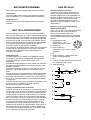
WHAT IS PLASMA CUTTING?
The plasma arc is a very hot arc obtained by
constricting a ionized gas into the small hole of the
torch tip. By limiting the arc width it is possible to
achieve very high temperatures (over 15.000 C°) and
very high velocity of the gas. The high temperature
melts the part to cut while the high speed of the gas
removes the molten metal from the workpiece.
The ideal gas to use for plasma is an inert gas, but
also compressed air can be used. However, the
presence of oxygen in the compressed air has to be
taken in consideration when designing the torch.
Plasma cutting torch
The plasma cutting torch is somehow similar to a TIG
torch but it is designed in such a way to force the arc
in a very small orifice in the torch tip.
The electrode is made with copper and at the end
there is a small part made with hafnium. The tip is
made with copper.
The compressed air goes through the torch and it is
used for creating the plasma gas and to cool the torch.
The arc ignition is obtained with a high frequency
discharge between the electrode and the tip (Pilot
Arc). The pilot arc is limited to max 3 seconds to
prevent heating of the torch and excessive wear on
the consumable parts.
When the torch is positioned close to the workpiece
the arc is transferred to the workpiece, the pilot arc
switches off and the cutting operation starts.
Cutting metal nets and grills
When the arc is transferred on the workpiece and the
cutting operation is started, it is necessary to move the
torch ahead constantly in order to have always the arc
between the torch and the solid metal. Otherwise, yhe
arc will switch off. The same would happen, if the
torch is moved away from the workpiece.
If it is necessary to cut a metal net or a grill or other
discontinuous materials the “Grid” option has to be
used by pushing the relevant key pad on the front
panel. In this mode the machine will always keep the
pilot arc on, thus preventing the arc from switching off.
In this cutting mode, however, the consumables and
parts of the torch will wear faster and the efficiency of
the cutting operation will decrease.
INITIAL INSTRUCTIONS
Connection to the net
Make sure the input voltage is correct. It should fit the
voltage specified at the type plate of the machine. The
machine is ready for use after the mains plug has
been mounted by autorised and qualified personnel.
The machine can be switched on and off at the mains
plug.
Connection of remote control
(ZETA 100 AUTOMAT)
ZETA 100 machines for automat use equipped with 8-
pole control interface can be controlled via a remote
control or a welding robot. The remote control socket
has terminals for the following functions:
A: Input signal for welding current, 0 –
+10V input impedance: 1Mohm
B: Signal ground
C: Arc detect – contact of relay (max.
1Amp), fully insulated
D: N.C.
E: Arc detect – contact of relay (max. 1Amp), fully
insulated
F: N.C.
G: Supply +24VDC. Short circuit protected with PTC
resistor (max. 50mA).
H: Supply ground
Generator operation
Connection to generators can damage the plasma
cutting machine.
When connected to a plasma cutting machine,
generators can produce large voltage pulses, which
can damage the plasma cutting machine. Use only
frequency and voltage stable generators of the
asynchronous type.
Defects on the plasma cutting machine arisen due to
connection of a generator are not included in the
guarantee.

15
Supply of compressed air
The compressed air hose has to be connected to the
back of the power source. The air should be clean and
dry in order to prevent fast wear of the torch parts. A
special air filter can be mounted in order to obtain this.
The compressor must have a capacity of at least
120 l/min by a pressure of 6-8 bar on ZETA 40/60 and
min. 180 l/min by a pressure of 6-8 bar on ZETA 100.
The compressor should not exceed 8 bar.
In the back of the power source there is an air filter
with a pressure gauge and a pressure regulator.
Adjustment of air pressure
The power source is equipped with a pressure switch
that will stop the machine if the input pressure goes
below 3 bar (see front panel above)
Switch ON the machine
Push the “air test” button on the front panel (the
gas valve will open)
Check the air pressure on the gauge and adjust it
to 3.5 bar while keeping the “air test” button
pushed. Different pressure values can be used
depending on the material type, thickness and the
Amperage. Do not exceed 6 bar.
Release the pushbutton
Cutting operation
Adjust the cutting current the value needed for the
material type and thickness.
Select cutting mode: normal or “grid”.
Keep the torch away from persons or objects and
push the torch trigger. The pilot arc will start.
Position the torch close to the workpiece and the arc
will be transferred. If the torch is not moved close to
workpiece within 3 seconds after the pilot arc has
been established, the pilot arc will switch off and the
operation has to be repeated.
Start the cutting operation from one end of the work-
piece in order to prevent slag and spatters to return on
the torch. If the cutting operation has to be started in
the middle of the workpiece angle the torch in order to
avoid return of slag or spatters on the torch.
The pilot arc will allow the transfer of the arc also on
dirty or painted workpiece.
Cutting speed
The correct cutting speed allows to completely cut the
material and to remove the molten material from the
opposite side of the workpiece, avoiding return of
sparks and spatters.
With the right cutting speed the flow of molten material
will have an angle of 10-15° on the torch axle. This will
allow cut edges clean without slag.
Too slow cutting speed widens the cutting area,
increases the heat-affected zone and leaves slag on
the cutting surface.
Too high cutting speed will not cut the whole thickness
of the material and will give return of spatters and
sparks.
During the cutting operation the torch has to be kept
perpendicular to the workpiece.
Advantages of plasma cutting
Plasma cutting gives many advantages over
oxyacetylene cutting. The heat-affected zone is
smaller while the high content of oxygen in oxycutting
prevents the use on stainless steel. The temperature
of plasma cutting is higher than oxycutting and the
flow of compressed air removes the molten material
leaving clean cut edges.
Plasma cutting can be used on all electrically
conductive materials.
Wear parts
There are 2 parts in the torch subject to wear: the
electrode and the tip.
The hafnium end of the electrode wears during cutting
and when this wear has reached 2-3 mm the electrode
has to be replaced. A worn out electrode will make
difficult to establish the pilot arc, will give an unstable
arc and worse cutting quality.
The tip has to be kept clean from spatters. The orifice
will become wider and irregular and this will decrease
the cutting quality.
The lifetime of the consumables is variable and
depends also from the application.
Torch and spares
Use only original spare and wear parts.
Please note!
It is important to control the flow by means of
the plasma gas test device.
The flow MUST be set between the two lines
on the gas test device.
If the flow is not within this area, it will result
in either bad cutting quality or decreased
lifetime on the wearing parts.

16
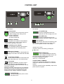
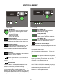
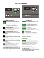
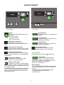
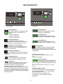
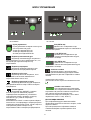
CONTROL UNIT
ZETA 40/60 ZETA 100
Control knob
The machine has a kontrol knob, which is
used for setting of the cutting current.
20-45A for ZETA 40,
20-60A for ZETA 60,
20-100A for ZETA100
Plasma arc indicator
The plasma arc indicator is illuminated for
reasons of safety and in order to show if there is
voltage at the output tap on the torch.
Overheating error indicator
The overheating indicator is illuminated if
cutting is interrupted due to overheating of the
machine.
Mains error indicator
The mains error indicator is illuminated if the
mains voltage is more than 15% lower than the rated
voltage.
Air pressure indicator
The air pressure indicator is illuminated if the
air pressure is less than 3 bar. The machine stops.
Torch alarm
RED light FLASHING: one short circuit is
present inside the torch (torch damaged or bad
assembling of electrical parts like electrode, tip, etc).
Generator is stopped.
RED light LIGHTED: head of torch is not completely
assembled. It informs the operator about the risk of
electric shock because of exposed electric parts
subjected to high voltage. Generator is stopped.
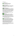
PLS (ZETA 100)
The text is displayed by short circuit in
the plasma torch.
LO.P (ZETA 100)
The text is displayed when the air
pressure from the air supply is too low.
HI.P (ZETA 100)
The text is displayed when the air
pressure from the air supply is too high.
Error symbols
The indicator next to the icon flashes on and
off when other types of errors occur. At the same
time an error symbol is shown in the display.
Selected error codes:
(The error code can be reset by pressing the
-key pad.)
Mains supply error
The icon will be displayed, when the
mains voltage is too high. E04-01 will
be shown when the mains voltage is too low.
Connect the welding machine to
400V AC, +/-15% 50-60Hz.
OTHER TYPES OF ERRORS
If other error symbols are displayed, the machine
needs to be switched off and then on to cancel the
symbol.
If the error symbol is shown repeatedly, repair of the
power source is required.

17
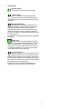
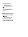
Cutting mode
Normal cutting
This function should be used in general.
“Grid” cutting
This function should only be used under
special conditions, as it will faster wear the
consumables of the torch and slow down the cutting
operation.
Gouging (ZETA 100)
This function is used with a special nozzle
that allows the plasma arc to blow away the
melted material and thereby creating a gouge.
During gouging the torch must be kept at 45° with
respect of workpiece and the operator must direct
the torch in a way that melted material will blow away
in a safe direction.
The pressure of compressed air should be regulated
to 3.5bar.
(ZETA 100)
This function offers the possibility to display
the arc voltage or the cutting current. The key
pad must be pressed for 3 seconds and the LED
next to the “A” indicator will be turned off, when the
arc voltage is displayed. To go back to the Cutting
Current just press the key pad again.
Air pressure test
By pushing this button the gas valve will open
without starting an arc. This operation allows
checking the air pressure on the gauge positioned on
the back of the machine and to adjust it to 3.5 bar for
ZETA 40/60. For ZETA 100 4.0 bar is recommended
for cutting and 3.5 bar for gouging.
In ZETA 100, when pressing the TEST AIR, the
display shows the pressure of compressed air.

18
MAINTENANCE
Insufficient maintenance may result in reduced
operational reliability and in lapse of guarantee.
The ZETA plasma cutting machines require virtually no
maintenance. However, exposure to extremely dusty,
damp or corrosive air is damaging to welding machines.
Periodical maintenance
In order to prevent problems arising, the following
procedure should be observed at least once a year or as
required.
- disconnect the machine from the mains supply and
wait 2 minutes before removing the front panels.
- clean the fan blades and the components in the cooling
pipe with clean, dry, compressed air.
Water separator
Empty and clean the water separator on the regulator.
This is carried out by pressing the air escape valve in
the bottom of the glass cap when the compressed air
is on, or by screwing the cap off and clean it.
The electrode and nozzle may become coated with
verdigris or short circuits between the electrode and
the cutting nozzle arise due to impurities in the air.
Moisture in the air prevents start of the pilot arc.
The end of the electrode and the inside of the nozzle
must be cleaned by fine sandpaper if impurities or
moisture in the cutting air have been present.
Plasma hose and cutting head
Examine
- Cutting head for damages.
- The plasma hose for damages on the cover
- and replace if needed nozzle, electrode and
electrode insulator.
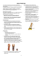
The nozzle must be cleaned frequently for metal
spatter by use of a wire brush. No sharp items must
be used, as they can damaged the hole in the nozzle.
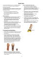
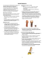
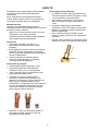
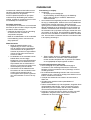
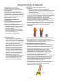
The nozzle is a wearing part, and it is important to
check for worn-out nozzles that need replacement.
There is a risk of a meltdown in the cutting head if the
nozzle is not exchanged in due time. The picture
below shows a new nozzle to the left and a worn-out
nozzle to the right. The nozzle is worn out when there
is a small crater in the hole.
Metal spatter between electrode and nozzle cap can
occur during cutting. This metal spatter must be
removed by blowing compressed air inside and at the
same time knocking easily at it.
Torch/ignition function (Zeta 100)
It is important to ensure that the ignition
mechanism is correctly movable each time the
electrode is exchanged. Lubrication is required
when the mechanism is not free on its
movement.
The picture below shows where to put grease
and how to push up and down to lubricate the
internal mechanism.
Remove the remaining grease before
reassembly of the torch.
We recommend pure Vaseline without
solvents or Paraffin oil.
Other lubricants are not allowed because they
can contain solvents like Toluene, Xylene,
Benzene (especially spray dispensers) that
can destroy inner parts of torch mechanism.
Silicon-based, Lithium-based and Teflon-
based products are NOT allowed because
they can react with inner rubber parts of torch.

19
TECHNICAL DATA
Power source: ZETA 40 ZETA 60 ZETA 100
Mains volta
g
e
(
50Hz-60Hz
)
1 x 230 V ±15% 3x400 V ±15% 3 x 400 V ±15%
Fuse 16 A 10 A 20 A
Mains current, effective 16.8 A 6.8 A 19.1 A
Power, (100%) 3.9 kVA 4.7 kVA 13.2 kVA
Power, max 5.3 kVA 7.4 kVA 29.9 kVA
Open circuit powe
r
< 35 W < 35 W < 35 W
Efficienc
y
0.9 0.9 0.8
Permitted load: Cuttin
g
Gougin
g
100% duty cycle (40°C ambient temp) 35 A / 94 V 40A / 96 V 75 A / 110 V 75 A / 130 V
60% duty cycle (40°C ambient temp) 40 A / 96 V 50 A / 100 V 85 A / 114 V 85 A / 134 V
40% duty cycle (40°C ambient temp) 45 A / 98 V 60 A / 104 V 100 A / 120 V -
35% duty cycle (40°C ambient temp) - - - 100 A / 140 V
100% dut
y
c
y
cle
(
20°C ambient temp
)
40 A / 96 V 45 A / 98 V - -
60% duty cycle (20°C ambient temp) 45 A / 98 V 55 A / 102 V - -
Open circuit voltage 225 V 241 V 248 V
Current range 20-45 A 20-60 A 20-100 A
1
Application class
S
S
S
2
Protection class
(
IEC 529
)
IP 23 IP 23 IP 23
Standards EN/IEC60974-1
EN/IEC60974-10 (Class A)
Dimensions (hxwxl) (mm) 360x220x570 360x220x570 405x345x675
Wei
g
ht 26k
g
27 k
g
36k
g
Cut qualit
y
8 mm 12 mm <25 mm
Cut max. 12 mm 18 mm <35 mm
Dispose of the product according to
local standards and regulations.
www.migatronic.com/goto/weee
1
S
The machine meets the standards which are demanded of machines working in areas where there is an increased risk of electric shock
2 Equipment marked IP23 is designed for indoor and outdoor applications

20
WARRANTY CONDITIONS
Migatronic welding machines are quality-tested
continuously throughout the production process and
undergo a thorough, quality-assured final function
test as assembled units.
The warranty period is 12 months for new welding
machines if no registration is carried out.
Upon registration of new welding machines within
6 weeks from invoicing, the warranty period is
extended to 24 months.
Registration must be made on the online address:
www.migatronic.com/warranty. The certificate of
registry is proof of the registration and will be sent by
e-mail. The original invoice and the certificate of
registry will document to the buyer that the welding
machine falls within the scope of a 24 months
warranty period.
If registration is not made, the standard warranty
period is 12 months for new welding machines, as
from the date of invoicing to end user. The original
invoice is documentation for the warranty period.
Migatronic provides warranty according to the
warranty conditions in force through remedying
defects in the welding machines that can be proved
to be caused by improper materials or workmanship
in the warranty period.
As a main rule, warranty is not provided for welding
hoses as they are considered to be wear parts;
defects that occur within 6 weeks after putting into
operation and which are caused by improper
materials or workmanship will, however, be
considered warranty claims.
All forms of transport in connection with a warranty
claim fall outside the scope of Migatronic’s warranty
and will take place for buyer’s own account and risk.
We refer to Migatronic’s warranty conditions at
www.migatronic.com/warranty
Leht laaditakse ...
Leht laaditakse ...
Leht laaditakse ...
Leht laaditakse ...
Leht laaditakse ...
Leht laaditakse ...
Leht laaditakse ...
Leht laaditakse ...
Leht laaditakse ...
Leht laaditakse ...
Leht laaditakse ...
Leht laaditakse ...
Leht laaditakse ...
Leht laaditakse ...
Leht laaditakse ...
Leht laaditakse ...
Leht laaditakse ...
Leht laaditakse ...
Leht laaditakse ...
Leht laaditakse ...
Leht laaditakse ...
Leht laaditakse ...
Leht laaditakse ...
Leht laaditakse ...
Leht laaditakse ...
Leht laaditakse ...
Leht laaditakse ...
Leht laaditakse ...
Leht laaditakse ...
Leht laaditakse ...
Leht laaditakse ...
Leht laaditakse ...
Leht laaditakse ...
Leht laaditakse ...
Leht laaditakse ...
Leht laaditakse ...
Leht laaditakse ...
Leht laaditakse ...
Leht laaditakse ...
Leht laaditakse ...
Leht laaditakse ...
Leht laaditakse ...
Leht laaditakse ...
Leht laaditakse ...
Leht laaditakse ...
Leht laaditakse ...
Leht laaditakse ...
Leht laaditakse ...
Leht laaditakse ...
Leht laaditakse ...
Leht laaditakse ...
Leht laaditakse ...
Leht laaditakse ...
Leht laaditakse ...
Leht laaditakse ...
Leht laaditakse ...
Leht laaditakse ...
Leht laaditakse ...
Leht laaditakse ...
Leht laaditakse ...
Leht laaditakse ...
Leht laaditakse ...
Leht laaditakse ...
Leht laaditakse ...
Leht laaditakse ...
Leht laaditakse ...
Leht laaditakse ...
Leht laaditakse ...
Leht laaditakse ...
Leht laaditakse ...
Leht laaditakse ...
Leht laaditakse ...
Leht laaditakse ...
Leht laaditakse ...
Leht laaditakse ...
Leht laaditakse ...
Leht laaditakse ...
Leht laaditakse ...
-
 1
1
-
 2
2
-
 3
3
-
 4
4
-
 5
5
-
 6
6
-
 7
7
-
 8
8
-
 9
9
-
 10
10
-
 11
11
-
 12
12
-
 13
13
-
 14
14
-
 15
15
-
 16
16
-
 17
17
-
 18
18
-
 19
19
-
 20
20
-
 21
21
-
 22
22
-
 23
23
-
 24
24
-
 25
25
-
 26
26
-
 27
27
-
 28
28
-
 29
29
-
 30
30
-
 31
31
-
 32
32
-
 33
33
-
 34
34
-
 35
35
-
 36
36
-
 37
37
-
 38
38
-
 39
39
-
 40
40
-
 41
41
-
 42
42
-
 43
43
-
 44
44
-
 45
45
-
 46
46
-
 47
47
-
 48
48
-
 49
49
-
 50
50
-
 51
51
-
 52
52
-
 53
53
-
 54
54
-
 55
55
-
 56
56
-
 57
57
-
 58
58
-
 59
59
-
 60
60
-
 61
61
-
 62
62
-
 63
63
-
 64
64
-
 65
65
-
 66
66
-
 67
67
-
 68
68
-
 69
69
-
 70
70
-
 71
71
-
 72
72
-
 73
73
-
 74
74
-
 75
75
-
 76
76
-
 77
77
-
 78
78
-
 79
79
-
 80
80
-
 81
81
-
 82
82
-
 83
83
-
 84
84
-
 85
85
-
 86
86
-
 87
87
-
 88
88
-
 89
89
-
 90
90
-
 91
91
-
 92
92
-
 93
93
-
 94
94
-
 95
95
-
 96
96
-
 97
97
-
 98
98


Migatronic ZETA 60 Kasutusjuhend
- Kategooria
- Keevitussüsteem
- Tüüp
- Kasutusjuhend
teistes keeltes
- Deutsch: Migatronic ZETA 60 Benutzerhandbuch
- italiano: Migatronic ZETA 60 Manuale utente
- svenska: Migatronic ZETA 60 Användarmanual
- français: Migatronic ZETA 60 Manuel utilisateur
- dansk: Migatronic ZETA 60 Brugermanual
- Nederlands: Migatronic ZETA 60 Handleiding
Seotud paberid
Muud dokumendid
-
Telwin TEL034 Kasutusjuhend
-
 Strongline SLW202 Kasutusjuhend
-
ESAB PT-36 Mechanized Plasmarc Cutting Torch Kasutusjuhend
-
 Strongline SLW204 Kasutusjuhend
-
ESAB PT-25 Plasma Arc Cutting Torch Kasutusjuhend
-
-
-
ESAB Powercut 650 Portable Plasma Cutting System Kasutusjuhend
-
-

