Legrand LP8S-8-115 Kasutusjuhend

Tüüp
Kasutusjuhend
Wattstopper
®
Lighting Control Panel
Quick Start Guide
No:24279 – 03/21 rev. 1
Catalog Number: LP8
Country of Origin: Made in United States BAA/TAA Compliant
INSTALLATION
1. Loosen the enclosure’s front cover screws (about 1/4”). Do not remove the screws. Lift the
cover and pull it toward you to remove it from the enclosure.
2. Remove the panel interior and set it aside.
3. Mount the panel enclosure to the wall using appropriate hardware (not provided).
4. Note the entry areas for low and line voltage in the picture. Install conduit into the
designated areas of the enclosure.
5. Reinstall the panel interior using the original hardware.
6. Connect the power supply (lower left corner) to the line voltage power source. Note the
allowable voltages printed on the unit.
7. Note the entry areas for low and line voltage in the picture below. Install conduit into the
designated areas of the enclosure.
8. Reinstall the panel interior using the original hardware.
9. Connect the power supply (lower left corner) to the line voltage power source. Note the
allowable voltages printed on the unit.
2
EM-24A2 Photocell Connections
Relay Control
Push-buttons
Accessory Power Connections
Power Supply Connections
Relay Switch and Pilot Connections
Relay Line and
Load Connections
Keypad and Display Door (open)
Optional Group Switching
(GS) Card
PANEL INTERIOR COMPONENTS AND CONNECTIONS
W
B
Y
R
W
B
Y
R
W
B
Y
R
W
B
Y
R
W
B
Y
R
W
B
Y
R
W
B
Y
R
W
B
Y
R
277V
115V
NEUT
GND
1
2
3
4
5
6
7
8
Clock Screen
Group switch
card (“GS” Option)
Interior door latches
(Two black plastic
self-retained
pop-fasteners)
Pull to release.
Press to latch.
Ground
Neutral
Line
ABCD EFGH
Power
supply
ACC. POWER
24VDC
24VR
24VAC
WHITE
YELCOM
24VR
24VAC
WHITE
RELAY PILOT
Relay status LEDs (8)
Relay control push-buttons (8)
The exterior panel cover is
hinged in the center - the low
voltage side is latched for
easy access; the line voltage
side is screwed down for safety.
Inside the panel, all low voltage
terminals are below a hinged
metal door on which the
clock screen display and
programming keypad
are mounted.
HELP
Observe correct voltage as marked on power supply.
Line
Voltage
Wiring
Section
Group channel control
push-buttons (8)
3
GENERAL INSTALLATION INFORMATION
All power must be turned off prior to wiring, installation or service.
More than one disconnect may be required to de-energize power to the LP8.
External circuit protection to the LP8 is required (for example, circuit breaker).
Installation shall be in accordance with all applicable regulations, wiring practices, and
codes.
Care should be taken to separate high voltage power from low voltage (Class 2) control
wiring.
Do not energize wiring until the unit is fully assembled and connected circuits have been
tested and found to be free of electrical shorts.
WARNING: TURN THE POWER OFF AT THE
CIRCUIT BREAKER BEFORE WIRING.
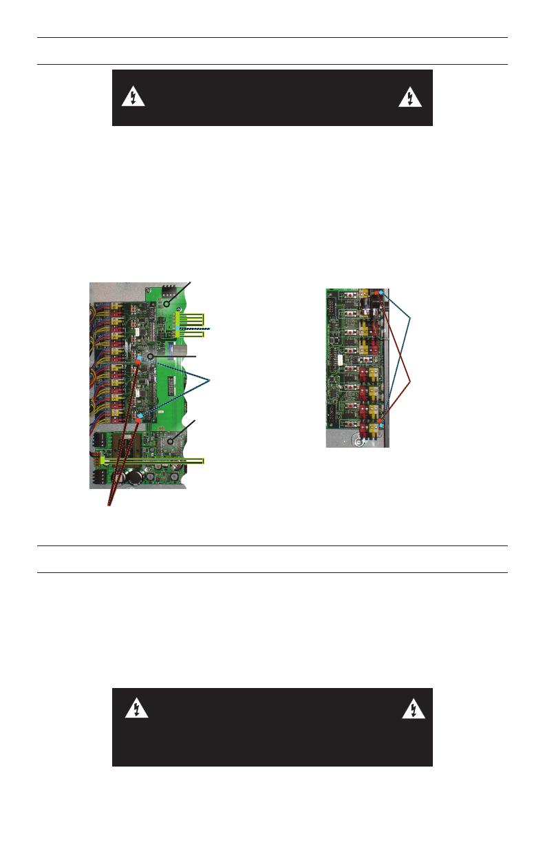
Status LEDs (7)
Solid Green (4)
Power LEDs (2)
Solid Green
Solid Green (2)
Blinking Blue (1)
Relay Driver (RD)
boards (2)
Flashing Blue
(at DS6)
Power Supply
(PS) board
C8 (motherboard)
Blinking Amber on RD board
(at DS7) = trouble condition
Flashing
Blue
LEDs (2)
= normal
operation
Group Switch Card (optional)
Blinking
Amber
LEDs (2)
= trouble
condition
POWER UP AND TEST
1. Power up the panel.
2. Complete the tests in the table.
3. Upon completing and passing all tests, power down the panel.
4. Install, connect, and test low voltage devices, contactors and loads to the panel per the
instructions referenced in the Resources section below.
5. Program the clock per your application requirements and record relay schedules and
scenario information on the Programming Record Sheet.
WARNING: IMPROPER INSTALLATION OR
CONNECTION OF THE LP8 MAY RESULT
IN SERIOUS PERSONAL INJURY AND/OR
DAMAGE TO THE LP8 AND OTHER DEVICES..
4
Test Response Result
What next?
If the panel continues to fail a test,
call Technical Support.
1
Observe the Blue
Status LED on the
C8 board
Blue LED blinks at a
regular tempo.
Pass Go to next Test.
Blue LED off or
continuously lit.
Fail Reset panel power. Check LED again.
2
Observe Blue LED
(at DS6) on RD
boards (and on GS
card if installed)
Blue LED flashes at
regular intervals on
both boards.
Pass Go to next Test.
Blue LED off or
continuously lit.
Fail Reset panel power. Check LED again.
3
Observe the Green
Status LEDs on the
C8 board
All 6 Green
Status LEDs are
continuously lit.
Pass Go to next Test.
Any Green Status
LED is off.
Fail Reset panel power. Check LEDs again.
4
Observe the two
green Power LEDs
at DS1 & DS2 on the
PS board
Both green
Power LEDs are
continuously lit.
Pass Go to next Test.
Either Green Power
LED is off.
Fail
Turn off power to panel and check red and
black wire connections to the J2 terminal
block on the PS board. Reset panel
power. Check LEDs again.
5
Look for any lit
Amber LEDs on
the RD (and GS if
installed).
No Amber LEDs
observed.
Pass Go to next Test.
An Amber LED is lit
or blinking.
Fail
Reset panel power. Check for Amber
LEDs again.
6
Relay Operation:
Press each Relay
control push-button
Red LED for each
relay lights and
relay clicks. Press
button again, relay
clicks and Red LED
goes off.
Pass
Ok to wire low voltage devices to relay
card terminals. See Resources list
for wiring and accessory installation
instructions.
Red LED doesn’t
light and/or relay
doesn’t click.
Fail
Make sure a jumper is installed on PS
board between YELCOM and 24VR
terminals.
5
RESOURCES
The following instructional tools are available:
1. Wiring loads and accessories: LP Series Installation & Wiring Reference (included with
the panel): Detailed LP8 wiring instructions for relays/contactors and loads, as well as low
voltage controls wiring and Group Switch card smartwiring procedures.
2. Low voltage control device installation instructions: Provided in the box with optional
products.
3. LP8 Programming: LP Series User Guide (included with the panel).
4. Instructions for individual clock screens:
Press the HELP button on the panel’s clock keypad.
5. Keeping records of circuit and relay schedules and programming selections: LP8
Programming Record Sheet (included with the panel).
6. Technical support: Visit our website – see the downloads page for new materials, FAQ
area, or call 800.879.8585.
HELP
SELECT
RAISE
LOWER
after
before
On/ Off/
Open:_______ thru:_______
On/ Off/
Open:_______ thru:_______
Blink before off? No Yes
Time Delay/Sweep Interval: _____min.
On _____ min. Sunset
after
before
On/ Off/
Open:_______ thru:_______
On/ Off/
Open:_______ thru:_______
after
before
On/ Off/
Open:_______ thru:_______
On/ Off/
Open:_______ thru:_______
after
before
after
before
On/ Off/
Open:_______ thru:_______
On/ Off/
Open:_______ thru:_______
after
before
c Photo & Sched On/Off
c Astronomic On/Off
c Astro & Sched On/Off
c Manual On/Sched Off
c Scheduled On/Off
c Man On/AS Sweep Off
c Photocell On/Off
c Photo & Sched On/Off
c Astronomic On/Off
c Astro & Sched On/Off
c Manual On/Sched Off
c Scheduled On/Off
c Man On/AS Sweep Off
c Photocell On/Off
c Photo & Sched On/Off
c Astronomic On/Off
c Astro & Sched On/Off
c Manual On/Sched Off
c Scheduled On/Off
c Man On/AS Sweep Off
c Photocell On/Off
c Photo & Sched On/Off
c Astronomic On/Off
c Astro & Sched On/Off
c Manual On/Sched Off
c Scheduled On/Off
c Man On/AS Sweep Off
c Photocell On/Off
c Photo & Sched On/Off
c Astronomic On/Off
c Astro & Sched On/Off
1 2
3
4
5
800.879.8585
www.legrand.us/wattstopper
No. 24279 – 03/21 rev. 1
© Copyright 2021 Legrand All Rights Reserved.
© Copyright 2021 Tous droits réservés Legrand.
© Copyright 2021 Legrand Todos los derechos reservados.
WARRANTY INFORMATION
Wattstopper warranties its products to be free of defects in materials and workmanship for a period of five (5)
years. There are no obligations or liabilities on the part of Wattstopper for consequential damages arising out of,
or in connection with, the use or performance of this product or other indirect damages with respect to loss of
property, revenue or profit, or cost of removal, installation or reinstallation.
  • Page 1 1
  • Page 2 2
  • Page 3 3
  • Page 4 4
  • Page 5 5
  • Page 6 6

Legrand LP8S-8-115 Kasutusjuhend

Tüüp
Kasutusjuhend

teistes keeltes