Murray Lawn Mower 405628x51A Kasutusjuhend
- Tüüp
- Kasutusjuhend

OPERATOR’S MANUAL
en
it
nl
da
de
fi
lv
Instruction Book - Riding mower
Istruzioni per l’uso - Trattore tagliaerba
Gebruikshandleiding - Zitmaaier
Driftsvejledning - Plænetraktor
Betriebsanleitung - Aufsitzmäher
Käyttöohjeet - Ajettava ruohonleikkuri
Instrukciju grāmata - Braucošs pļāvēja
Juhend - Traktorniiduki
Használati Útmutató - Önjáró fûnyíró gép
Användarhandbok - Trädgårdtraktor
Bruksanvisning - Rider
Manual Part No. 7102049
Revision 00
Rev. Date 02/2008
TP 199-4814-00-RD-R
CAUTION: Read and
follow all instructions.
Model No. 405628x51A
Product Type
Mfg. No. Description
7800281 40” Murray CE Riding Mower
et
hu
sv
no

2
7102049
1
1
2
3
4 (17x192)
6
7 (17x195)
5 (30x49)
2
1
2
3
4 (17x47)
5 (1001054)
1
2
3
7
6 (17x146)
4 (25x3)
3
5
1
3
4
2
6
8
6 (2x82)
7 (14x79)
4
3
1
2
4
5
7
5
1
2
6
1
2
3
4
5
6
7
7
1
8
2
6
1
2
3
4
5
9
4
5
4
6
1
2
3
7
10
11
12
1
10
11
6
5
4
12
1
2
13
3
1
2
14 15

3
7102049
2
1
6
5
7
5
9
7
4
5
8
13
16
3
2
1
17
1
2
5
18
432
1
19
4
2
1,3
1,2
20
7
1
2
6
3
4
1/4” (6mm)
7
3
21
1
2
3
3
4
4
5
6
7
8
9
22

4
7102049
12 3
4
5
6
7
8
23
9
MAX 90N
+
MAX 150N
+
10 11
12
13
1
2
3
4
5
67
8
9
10 11 12
13
14
15
24
1001054
2x82
14x79
17x47
20729
30x49
17x195
17x192
17x146
25x3
25

en
5
7102049
CONTENTS
INTERNATIONAL PICTORIALS 5
LIMITED WARRANTY 6
OWNER’S INFORMATION 7
SAFE OPERATION PRACTICES 7
ASSEMBLY 8
OPERATION 9
MAINTENANCE CHART 11
MAINTENANCE 11
TROUBLE SHOOTING CHART 14
INTERNATIONAL PICTORIALS
IMPORTANT: The following pictorials are lo-
cated on your unit or on literature supplied
with the product. Before you operate the
unit, learn and understand the purpose for
each pictorial.
NOTE: Illustrations and pictorials begin
on page 2.
Safety Warning Pictorials (Figure 23)
1 WARNING
2 IMPORTANT: Read Owner’s Manual
Before Operating This Machine.
3 WARNING: Thrown Objects. Keep
Bystanders Away. Read User Instructions
Before Operating This Machine.
4 WARNING: Do Not Use This Machine On
Slopes Greater Than 10 Degrees.
5 DANGER: Keep People, Especially
Children, Away From Unit.
6 DANGER: No Step.
7 DANGER: Keep Feet And Hands Away
From Rotating Blade.
8 DANGER: Disconnect Spark Plug Wire
Before Servicing Unit.
9 WARNING: Hot Surface.
10 WARNING: Use Caution When Connecting
Or Disconnecting Accessories.
11 WARNING: Crushed Fingers.
12 IMPORTANT: Follow Instructions In
Owner’s Manual To Level The Deck.
13 WARNING: Stay Clear Of Mower Blade As
Long As Engine Is Running.
Control And Operating Pictorials
(Figure 24)
1 Engine Start
2 Lights
3 Engine Run
4 Engine Stop
5 Engine Run
6 Brake
7 Parking Brake
8 Clutch
9 Slow
10 Fast
11 Choke
12 Oil
13 Blade Rotation Control
14 Raise
15 Fuel

en
6
7102049
BRIGGS & STRATTON CORPORATION OWNER WARRANTY POLICY
Effective January 1, 2006 replaces all undated Warranties and all Warranties dated before January 1, 2006
Briggs & S tratton Corporation will repair or replace, free of charge, any part(s) of the product that is defective in material or workmanship or both.
Transportation charges on product submitted for repair or replacement under this warranty must be borne by purchaser. This warranty is effective
for the time periods and subject to the conditions stated below. For warranty service, find the nearest Authorized Service Dealer in your area. For
warranty service, find the nearest Authorized Servic e Dealer in our dealer locator map at www.murray.com.
THERE IS NO OTHER EXPRESS WARRANTY. IMPLIED WARRANTIES, INCLUDING THOSE OF MERCHANTABILITY AND FITNESS FOR A
PARTICULAR PURPOSE, ARE LIMITED TO ONE YEAR FROM PURCHASE, OR TO THE EXTENT PERMITTED BY LAW ANY AND ALL
IMPLIED WARRANTIES ARE EXCLUDED. LIABILITY FOR INCIDENTAL OR CONSEQUENTIAL DAMAGES ARE EXCLUDED TO THE
EXTENT EXCLUSION IS PERMITTED BY LAW. Some states or countries do not allow limitations on how long an implied warranty lasts, and
some states or countries do not allow the exclusion or limitation of incidental or consequential damages, so the above limitation and exclusion
may not apply to you. This warranty gives you specific legal rights and you may also have other rights which vary from state to state or country to
country.
LIMITED WARRANTY
WARRANTY TERMS
Consumer Commercial Condition of
Brand / Unit Use Use Warranty Term
Riders / Tractors 2 years 90 days..................... ...........
The warranty period begins on the date of purchase by the first retail consumer or commercial end user, and continues for the period of
time stated in the table above. “Consumer use” means personal residential household use by a retail consumer. “Commercial use” means
all other uses, including use for commercial, income producing or rental purposes. Once product has experienced commercial use, it shall
thereafter be considered as commercial use for purposes of this warranty.
No warranty registration is necessary to obtain warranty on Murray branded products. Save your proof of purchase receipt. If you do not
provide proof of the initial purchase date at the time warranty service is requested, the manufacturing date of the product will be used to
determine the warranty.
ABOUT YOUR WARRANTY
We welcome warranty repair and apologize to you for being inconvenienced. Any Authorized Service Dealer may perform warranty
repairs. Most warranty repairs are handled routinely, but sometimes requests for warranty service may not be appropriate. For example,
warranty service would not apply to the product if damage occurred because of misuse, lack of routine maintenance, shipping, handling,
warehousing or improper installation. Similarly, the warranty is void if the serial number on the product has been removed or the product
has been altered or modified.
This warranty covers product related defective material and/or workmanship onl y. To avoid misunderstanding which might occur be-
tween the customer and the Dealer, listed below are some of the causes of product failure that the warranty does not cover.
• Normal Wear: Small Engine Powered Equipment, like all mechanical devices, needs periodic parts and service to perform well. Warranty does not
cover repair when normal use has exhausted the life of the product or part.
• Installation: This warranty does not apply to product that has been subjected to improper or unauthorized installation, alteration or modification. Nor
installations that prevent starting, cause unsatisfactory engine performance.
• Improper Maintenance: The life of this product depends upon the conditions under which it operates, and the care it receives. Recommended
maintenance and adjustment intervals are stated in the Operator’s Manual. Often product, such as tillers, edgers, rotary mowers, are used in dusty
or dirty conditions, which can cause what appears to be premature wear. Such wear, when caused by dirt, dust, or other abrasive material entering
the product because of improper maintenance is not covered by warranty. The warranty will not cover repairs due to problems caused by replace-
ment parts that are not original manufactured part(s).
• Incorrect and/or insufficient fuel or lubrication: This warranty does not cover damage caused by the use of stale fuel, or altered gasolines. Dam-
age to engine or engine components ie, combustion chamber, valves, valve seats, valve guides, burned starter motor windings caused by use of
alternate fuels such as liquified petroleum, natural gas, are not covered unless engine is certified for this operation. Parts which are scored or bro-
ken because product was operated with insufficient, contaminated or incorrect grade of lubricating oil as well as product components damaged due
to lack of lubrication are not covered.
• Operational Misuse: Proper operation of the product is s tated in the Operator’s Manual. Product damaged by overspeeding, overheating, or opera-
tion in a confined area without sufficient ventilation. Product broken by excessive vibration caused by a loose engine mounting, loose or unbalanced
blades, impellers, overspeeding, or bent crankshaft due to striking of solid object. Damage or malfunctions resulting from accidents, abuse, or im-
proper servicing or freezing or chemical deterioration, as well as operating in excess of recommended capacities as outlined in the Operator’s
Manual are not covered.
• Routine tune-up, wear items or adjustments: This warranty excludes wear items such as oil, belts, blades, o-rings, filters, etc.
• Other exclusions: Repair or adjustments for part(s) that are not manufactured by Briggs & Stratton Corporation, are not covered, see warranty for
respective manufacturers. This warran ty excludes failures due to acts of God and other force majeure events beyond the manufacturers con-
trol. Also excluded are used, reconditioned, and demonstration products.
W arranty service is available only through Authorized Service Dealers. Locate your nearest dealer in our locator map at www .murray.com.

en
7
7102049
OWNER’S INFORMATION
Know your product: If you understand the unit
and how the unit operates, you will get the best
performance. As you read this manual, compare
the illustrations to the unit. Learn the location
and the function of the controls. To help prevent
an accident, follow the operating instructions
and the safety rules. Keep this manual for future
reference.
WARNING: Look for this symbol to indicate
important safety precautions. This symbol
indicates: “Attention! Become Alert! Your
Safety Is At Risk.”
Responsibility Of The Owner
WARNING: This cutting machine is
capable of amputating hands and
feet and throwing objects. Failure
to observe the following safety instructions
could result in serious injury or death to
the operator or bystanders.
The responsibility of the owner is to
follow the instructions below.
SAFE OPERATION PRACTICES
For Ride--On (Riding)
Rotary Mower Machines
Training
1. Read the instructions carefully. Be familiar
with the controls and the proper use of the
equipment.
2. Never allow children or people unfamiliar
with these instructions to use the mower.
Local regulations may restrict the age of
the operator.
3. Never mow while people, especially
children, or pets are nearby.
4. Keep in mind that the operator or user is
responsible for accidents or hazards occur-
ring to other people or their property.
5. Do not carry passengers.
6. All drivers should seek and obtain pro-
fessional and practical instruction. Such
instruction should emphasize:
a. the need for care and concentration
when working with ride--on machines;
b. control of a ride--on machine sliding
on a slope will not be regained by the
application of the brake. The main
reasons for loss of control are:
• insufficient wheel grip;
• being driven too fast;
• inadequate braking
• the type of machine is unsuitable
for its task;
• lack of awareness of the effect of
ground conditions, especially
slopes;
• incorrect hitching and load dis-
tribution.
Preparation
1. While mowing, always wear substantial
footwear and long trousers. Do not operate
the equipment when barefoot or wearing
open sandals.
2. Thoroughly inspect the area where the
equipment is to be used and remove all ob-
jects which may be thrown by the machine.
3. WARNING -- Petrol is highly flammable.
a. Store fuel in containers specifically de-
signed for this purpose.
b. Refuel outdoors only and do not
smoke while refuelling.
c. Add fuel before starting the engine.
Never remove the cap of the fuel tank
or add petrol while the engine is run-
ning or when the engine is hot.
d. If petrol is spilled, do not attempt to
start the engine but move the machine
away from the area of spillage and
avoid creating any source of ignition
until petrol vapours have dissipated.
e. Replace all fuel tanks and container
caps securely.
4. Replace faulty silencers.
5. Before using, always visually inspect to see
that the blades, blade bolts and cutter as-
sembly are not worn or damaged. Replace
worn or damaged blades and bolts in sets
to preserve balance.
6. On multi--blade machines, take care as ro-
tating one blade can cause other blades to
rotate.
Operation
1. Do not operate the engine in a confined
space where dangerous carbon monoxide
fumes can collect.
2. Mow only in daylight or in good artificial
light.
3. Before attempting to start the engine, dis-
engage all blade attachment clutches and
shift into neutral.
4. Do not use on slopes of more than 10 de-
grees.
5. Remember there is no such thing as a
“safe” slope. Travel on grass slopes re-
quires particular care. To guard against
overturning:
a. do not stop or start suddenly when
going up or downhill;
b. engage clutch slowly, always keep
machine in gear, especially when tra-
velling downhill;
c. machine speeds should be kept low
on slopes and during tight turns;
d. stay alert for humps and hollows and
other hidden hazards;
e. never mow across the face of the
slope, unless the mower is designed
for this purpose.
6. Use care when pulling loads or using heavy
equipment.
a. Use only approved drawbar hitch
points.
b. Limit loads to those you can safely
control.
c. Do not turn sharply. Use care when
reversing.
d. Use counterweight(s) or wheel
weights when suggested in the In-
struction Book.
7. Watch out for traffic when crossing or near
roadways.
8. Stop the blades rotating before crossing
surfaces other than grass.
9. When using any attachments, never direct
discharge of material toward bystanders
nor allow anyone near the machine while in
operation.
10. Never operate the mower with defective
guards or shields, or without safety protec-
tive devices in place.
11. Do not change the engine governor set-
tings or overspeed the engine. Operating
an engine at excessive speed may in-
crease the hazard of personal injury.
12. Before leaving the operator’s position
a. disengage the power take--off and
lower the attachments;
b. change into neutral and set the park-
ing brake;
c. stop the engine and remove the key.
13. Disengage drive to attachments, stop the
engine, and disconnect the spark plug
wire(s) or remove the ignition key
a. before cleaning blockages or unclog-
ging chute;
b. before checking, cleaning or working
on the mower;
c. after striking a foreign object. Inspect
the mower for damage and make re-
pairs before restarting and operating
the equipment;
d. if the machine starts to vibrate abnor-
mally (check immediately).
14. Disengage drive to attachments when
transporting or not in use.
15. Stop the engine and disengage drive to at-
tachment
a. before refuelling;
b. before removing the grass catcher;
c. before making height adjustment un-
less adjustment can be made from the
operator’s position.
16. Reduce the throttle setting during engine
run--out and, if the engine is provided with a
shut--off valve, turn the fuel off at the con-
clusion of mowing.
17. Before and when backing, look behind and
down for small children.
18. Use extra care when approaching blind
corners, shrubs, trees or other objects that
may obscure vision.
Maintenance and Storage
1. On multi--blade machines, take care as ro-
tating one blade can cause other blades to
rotate.
2. When machine is to be parked, stored or
left unattended, lower the cutting means
unless a positive mechanical lock is used.
3. Keep all nuts, bolts, and screws tight to be
sure the equipment is in safe working
condition.
4. Never store the equipment with petrol in the
tank inside a building where fumes may
reach an open flame or spark.
5. Allow the engine to cool before storing in
any enclosure.
6. To reduce the fire hazard, keep the engine,
silencer, battery compartment and petrol
storage area free of grass, leaves, or ex-
cessive grease.
7. Check the grass catcher frequently for
wear or deterioration.
8. Replace worn or damaged parts for safety.
9. If the fuel tank has to be drained, this
should be done outdoors.

en
8
7102049
ASSEMBLY
All fasteners are in the parts bag. Do not discard
any parts or material until the unit is assembled.
WARNING: Before doing any as-
sembly or maintenance to the
mower, remove the wire from the
spark plug.
NOTE: In this instruction book, left and right
describe the location of a part with the oper-
ator on the seat.
NOTE: Illustrations and pictorials begin on
page 2.
NOTE: To assemble the following loose
parts, use the fasteners shown at full size in
Figure 25.
How To Install The Front Wheels
(Figure 1)
Use a knife and cut the four sides of the con-
tainer. Install the front wheels (1) in the con-
tainer.
NOTE: Use a piece of wood about 4 feet (1.25
meters) long to raise the front of the tractor.
If a piece of wood cannot be found, get
another person to help lift the tractor. Be
careful, do not let the tractor fall.
1. Raise the front of the tractor. Set a support
(block of wood) under the tractor.
2. Make sure the valve stem (2) is to the out-
side of the tractor. Slide the front wheel (1)
on the spindle (3).
3. Fasten each front wheel (1) with washer (4)
and cotter pin (5). Bend the ends of the
cotter pin (5) appart to keep the front wheel
(1) on the spindle (3).
4. Fasten each front wheel (1) with washer (4)
and e--ring (5).
5. After the front wheels (1) are installed, lift
the tractor from the support. Roll the tractor
off of the container.
6. If your tractor has hub caps (6), install the
hub caps (6). Make sure the washers (4)
hold the hub caps (6) in place.
How To Install The Seat (Figure 2)
1. Carefully remove the plastic bag from the
seat (1).
2. Align the holes in the seat hinge (2) to the
holes in the seat (1). Fasten the seat (1) to
the seat hinge (2) with the fasteners (4) and
(5).
3. Check the operating position of the seat (1).
If the seat (1) needs to be adjusted, loosen
the two wing bolts (5). Slide the seat (1) for-
ward or backward along the seat adjusting
holes (3). Tighten the wing bolts (5).
How To Assemble The Steering Wheel
(Figure 3)
1. Make sure the front wheels point forward.
2. Slide the cover (3) over the steering post
(2). Make sure the collar of the cover (3) is
on top.
3. Slide the steering wheel (1) onto the steer-
ing post (2).
4. Attach the steering wheel (1) to the steer -
ing post (2) with screw (4) and washer (6).
5. Some models have an optional insert (7) in
the parts bag. Attach the insert (7) to the
centre of the steering wheel (1).
Maintenance Free Battery (Figure 4)
IMPORTANT: Before you attach the battery
cables to the battery, check the battery date.
The battery date tells if the battery must be
charged.
1. Check the top and the side of the battery (1)
for the location of the battery date.
2. If the battery (1) is put into service before
the , the battery cables can be attached with -
out charging the battery (1). See “How To
Install The Battery Cables”.
3. If the battery (1) is put into service after the ,
the battery (1) must be charged. See “How
To Charge The Maintenance Free Battery”.
How To Charge The Battery (Figure 4)
WARNING: When you charge the
battery, do not smoke. Keep the bat-
tery away from any sparks. The
fumes from the battery acid can cause an
explosion.
1. Remove the battery (1) and battery tray (3).
2. Remove the protective cap from the battery
terminal.
3. Use a 12 volt battery charger to charge the
battery (1). Charge at a rate of 6 amperes
for one hour. If you do not have a battery
charger, have an authorized service centre
charge the battery.
4. Install the battery (1) and battery tray (3).
Make sure the positive (+) terminal (4) is on
the left side.
How To Install The Battery Cables
(Figure 4)
WARNING: To prevent sparks, fasten
the red cable to the positive (+) ter-
minal before you connect the black
cable.
1. Remove the protective cap from the battery
terminal.
2. Slide the terminal cover (2) onto the red
cable (5). Fasten the red cable (5) to the
positive (+) terminal (4) with the fasteners
(6) and (7).
3. Fasten the black cable 8 to the negative (--)
terminal with the fasteners (6) and (7).
Check The Tyres
Check the air pressure in the tyres. Tyres with
too much air pressure will cause the unit to ride
rough. Also, the wrong air pressure will keep the
mower housing from cutting level. The correct
air pressure is: Front Tyres 0,97 BAR (14 PSI),
Rear Tyres 0,69 BAR (10 PSI). The tyres were
over inflated for shipment.
Check The Level Of The Mower
Housing
Make sure the level of cut is still correct. After
you mow a short distance, look at the area that
was cut. If the mower housing does not cut level,
see the instructions on “How To Level The
Mower Housing” in the Maintenance section of
this instruction book.
How To Prepare The Engine
NOTE: The engine was shipped from the fac-
tory filled with oil. Check the level of the oil.
Add oil as needed.
See the engine manufacturer’s instructions for
the type of petrol and oil to use. Before you use
the unit, read the information on safety, oper-
ation, maintenance, and storage.
WARNING: Follow the engine manu-
facturer’s instructions for the type o
f
petrol and oil to use. Always use a
safety petrol container. Do not smoke when
adding petrol to the engine. When inside an
enclosure, do not fill with petrol. Before you
add petrol, stop the engine. Let the engine
cool for several minutes.
Important! Before You Start Mowing
U Check the engine oil.
U Fill the fuel tank with petrol.
U Check the air pressure of the tyres.
U Check the level of the mower hous-
ing.
U Attach the battery cables.

en
9
7102049
OPERATION
NOTE: Illustrations and pictorials begin on
page 2.
Location Of Controls
(Figure 5, Figure 20 )
Blade Rotation Control (1): Use the blade rota-
tion control to start and stop the rotation of the
blade.
Brake Pedal (2): Use the brake pedal to quickly
stop.
Headlight Switch (3): The headlight switch is
the first part of the ignition switch. To use the
lights with the engine running, turn the key to the
position for the lights.
Ignition Switch (3): Use the ignition switch to
start and stop the engine.
Speed Control Pedal (4): Use the speed con-
trol pedal to change the speed and the direction
of the unit.
Lift Lever (5): Use the lift lever to change the
height of cut.
Parking Brake Lever (6): Use the parking brake
lever to engage the brake when you leave the
unit.
Throttle Control Lever (7): Use the throttle
control lever to increase or decrease the speed
of the engine.
(Figure 20) Automatic Drive disconnect (1):
use the automatic drive disconnect, located
under the seat, to disengage the transmission.
Attachments
This unit can use many different attachments.
This unit can pull attachments like a lawn
sweeper, a lawn aerator, or a hopper spreader.
This unit can not use attachments that engage
the ground like a plough, a disk harrow, or a
cultivator.
For trailer and pull--behind attachments, the
maximum weight is 113 k g (250 lbs.).
How To Use The Throttle Control
(Figure 5)
Use the throttle control (7) to increase or de-
crease the speed of the engine.
1. The FAST position is marked with a detent.
For normal operation and when using a
grass bagger, move the throttle control to the
FAST position. For maximum charging of the
battery and for a cooler running engine, oper-
ate the engine in the FAST position.
2. The engine governor is set at the factory for
maximum performance. Do not adjust the
governor to increase the speed of the en-
gine.
How To Use The Blade Rotation Control
(Figure 5)
Use the blade rotation control (1) to engage
the blade(s).
1. Before you start the engine, make sure the
blade rotation control (1) is in the DISEN-
GAGE position.
2. Move the blade rotation control (1) to the
ENGAGE position to rotate the blade(s).
NOTE: If the engine stops when you en-
gage the blade(s), the seat switch is not
activated. Make sure you sit in the middle
of the seat.
3. Move the blade rotation control (1) to the
DISENGAGE position to stop the blade(s).
Before you leave the operator’s position,
make sure the blade(s) has stopped rotating.
4. Before you ride the unit across a sidewalk or
a road, move the blade rotation control (1)
to the DISENGAGE position.
WARNING: Always keep your
hands and feet away from the
blade, deflector opening, and the
mower housing when the engine runs.
How To Use The Speed Control Pedal
(Figure 5)
The drive system uses a Hydrostatic Automatic
Drive transmission. The Hydrostatic trans-
mission is very easy to operate. This type of
drive system does not require a shift lever or a
clutch pedal.
The speed and direction of travel is controlled by
a single speed control pedal (4) operated with
your right foot. Do not use the left brake pedal in
normal operation. Only use the left brake pedal
to quickly stop in an emergency.
How To Drive Forward
1. (Figure 20) The automatic drive discon-
nect (1) must be in the DRIVE position (2).
2. Slowly release your left foot from the brake
pedal.
3. Move the throttle control to the FAST posi-
tion.
4. (Figure 19) Slowly push the speed control
pedal (1) forward (4) to the desired speed.
5. To increase forward speed, slowly move the
speed control pedal (1) forward. To reduce
forward speed, slowly release the speed
control pedal (1) until the unit slows to the
desired speed.
How To Drive In Reverse
1. Look to the rear.
2. Slowly push the speed control pedal (1) to
the REVERSE position (2).
How To Change Directions
CAUTION: To change directions, do not use
the left brake pedal. Use only the speed con-
trol pedal.
1. Slowly remove your foot from the speed
control pedal (1).Thespeed control pedal
(1) will automatically return to the NEUTRAL
position (3).
2. When the unit stops, slowly move the speed
control pedal (1) to the desired direction.
How To Disconnect The Transmission
(Figure 20)
To push the unit, use the automatic drive dis-
connect (1) to release the transmission. The
automatic drive disconnect (1) is under the
seat.
1. The engine must be off.
2. Raise the seat. The automatic drive dis-
connect (1) is under the seat.
3. Move and latch the automatic drive discon-
nect (1) in the PUSH position (3). The
transmission is now released and the unit
can be pushed.
NOTE: In cold weather, the heavy viscos-
ity oil in the transmission will make the
unit difficult to push.
4. To engage the transmission, unlatch the au-
tomatic drive disconnect (1). The trans-
mission is now connected and ready to
operate.
How To Use The Parking Brake
(Figure 5)
1. Completely push the brake pedal (2) for-
ward.
2. Lift the parking brake lever (6).
3. Remove your foot from the brake pedal (2)
and then release the parking brake lever
(6). Make sure the parking brake will hold the
unit.
4. To release the parking brake (6), completely
push the brake pedal (2) forward. The park-
ing brake will automatically release.
WARNING: Before you leave the
operator’s position, set the parking
brake. Move the blade rotation con-
trol to the DISENGAGE position. Stop the
engine and remove the ignition key.
How To Change The Cutting Height
(Figure 5)
To change the cutting height, raise or lower the
lift lever (5) as follows.
1. Move the lift lever (5) forward to lower the
mower housing and back to raise the mower
housing.
2. When you ride on a sidewalk or road, move
the lift lever (5) to the highest position and
move the blade rotation control to the DIS-
ENGAGE position.
How To Stop The Unit (Figure 5)
1. Slowly remove your foot from the speed
control pedal (4). The speed control pedal
(1) will automatically return to the NEUTRAL
position and the unit will stop.
2. Move the blade rotation control (1) to the
DISENGAGE position.
3. Set the parking brake (6).
WARNING: Make sure the parking
brake will hold the unit.
4. Move the throttle control (7) to the SLOW
position.
5. To stop the engine, turn the ignition key (3)
to the OFF position. Remove the key.
How To Transport The Unit
To transport the unit, follow the steps below.
1. Move the blade rotation control to the DIS-
ENGAGE position.
2. Raise the lift lever to the highest position.

en
10
7102049
3. Move the throttle control to a position be-
tween SLOW and FAST.
4. Slowly push the speed control pedal forward
to the desired speed.
How To Operate With The Mower
Housing
IMPORTANT: When you operate with the
mower housing, always operate with the
throttle control in the FAST position.
1. Start the engine.
2. Move the lift lever to a height of cut position.
In high or thick grass, cut the grass in the
highest position first and then lower the
mower housing to a lower position.
3. Move the throttle control to the SLOW posi-
tion.
4. Slowly move the blade rotation control to the
ENGAGE position.
5. Move the throttle control to the FAST posi-
tion.
6. Slowly push the speed control pedal to the
desired speed.
NOTE: When you mow in heavy grass or
mow with a bagger, use a slow forward
speed.
7. Make sure the level of cut is still correct.
After you mow a short distance, look at the
area that was cut. If the mower housing does
not cut level, see the instructions on “How To
Level The Mower Housing” in the Mainten-
ance section.
WARNING: For better control of the
unit, select a safe speed.
How To Operate On Hills
WARNING: Do not ride up or down
slopes that are too steep to back
straight up. Never ride the unit
across a slope.
1. Control the speed only with the speed control
pedal. Do not use the brake pedal on a hill.
2. To help prevent an accident, slowly move the
speed control pedal. Avoid sudden turns or
changes in speed.
3. To reduce forward speed when going down a
hill, slowly release the speed control pedal
until the unit slows to the desired speed.
HowToStopOnaHill
1. Avoid stopping on a hill. If you must quickly
stop in an emergency, remove your right foot
from the speed control pedal and quickly de-
press the left brake pedal.
2. Set the parking brake.
3. Before you dismount from the seat, move the
throttle control to the SLOW position, move
the blade rotation controlattachment clutch to
the DISENGAGED position, turn off the en-
gine and set the parking brake.
How To Start Operation On A Hill
1. Start the engine
2. Move the blade rotation controlattachment
clutch to the ENGAGED position.
3. Move the throttle control to the FAST posi-
tion.
4. Depress the brake pedal and release the
parking brake. As you release the parking
brake, push the speed control pedal to the
desired speed.
Slowly push the speed control
pedal as you release the parking
brake. The parking brake must be
disengaged before the speed control pedal
is able to engage the transmission.
Before Starting The Engine
Check the oil
NOTE: The engine was shipped from the fac-
tory filled with oil. Check the level of the oil.
Add oil as needed. See the engine manufac-
turer’s instructions for the type of petrol and
oil to use.
1. Make sure the unit is level.
NOTE: Do not check the level of the oil
while the engine runs.
2. Check the oil. Follow the procedure in the
engine manufacturer’s instructions.
3. If necessary, add oil until the oil reaches the
FULL mark on the dipstick. The quantity of oil
needed from ADD to FULL is shown on the
dipstick. Do not add too much oil.
Add Petrol
WARNING: Always use a safety
petrol container. Do not smoke
when adding petrol to the fuel tank.
Do not add petrol when you are inside an
enclosure. Before you add petrol, stop the
engine and let the engine cool for several
minutes.
(Figure 6) Fill the fuel tank (1) to the FULL (2)
position with regular unleaded petrol. Do not use
premium unleaded petrol. Make sure the petrol
is fresh and clean. Leaded petrol will increase
deposits and shorten the life of the valves.
How To Start The Engine
WARNING: The electrical system
has an operator presence system
that includes a sensor switch for
the seat. These components tell the
electrical system if the operator is sitting
on the seat. This system will stop the
engine when the operator leaves the seat.
For your protection, always make sure this
system operates correctly.
NOTE: The engine will not start unless you
depress the clutch/brake pedal and move the
blade rotation control to the DISENGAGE
position.
1. Push the clutch/brake brake pedal complete-
ly forward. Keep your foot on the pedal.
2. Make sure the blade rotation control is in the
DISENGAGE position.
3. Move the throttle control completely forward
to the CHOKE or FAST position. Some mo-
dels have a separate choke knob. Pull the
choke knob to the full CHOKE position.
4. Turn the ignition key to the START position.
NOTE: If the engine does not start after
four or five tries, move the throttle control
to the FAST position. Again try to start the
engine. If the engine will not start, see the
TROUBLE SHOOTING CHART.
5. Slowly move the throttle control to the SLOW
position.
6. To start a hot engine, move the throttle con-
trol to a position between FAST and SLOW.
Mowing And Bagging Tips
1. For a lawn to look better, check the cutting
level of the mower housing. See “How To
Level The Mower Housing” in the Mainten-
ance section.
2. For the mower housing to cut level, make
sure the tyres have the correct amount of air
pressure.
3. Every time you use the unit, check the blade.
If the blade is bent or damaged, immediately
replace the blade. Also, make sure the nut
for the blade is tight.
4. Keep the blade(s) sharpened. Worn blades
will cause the ends of the grass to turn
brown.
5. Do not cut or bag grass that is wet. Wet
grass will not discharge correctly. Let the
grass dry before cutting.
6. Use the left side of the mower housing to trim
near an object.
7. Discharge the cut grass onto the mowed
area. The result is a more even discharge of
cut grass.
8. When you mow large areas, start by turning
to the right so that the cut grass will dis-
charge away from shrubs, fences, driveways,
etc. After one or two rounds, mow in the op-
posite direction making left turns until fin-
ished.
9. If the grass is very high, cut two times to de-
crease the load on the engine. First cut with
the mower housing in the highest position
and then lower the mower housing for the
second cut.
10.For better engine performance and an even
discharge of the cut grass, always operate
the engine with the throttle in FAST position.
11. When you use a bagger, operate the engine
with the throttle in FAST position and the
speed control pedal pushed 1/3 to 1/2 for-
ward..
12.After each use, clean the bottom and top of
the mower housing for better performance.
Also, a clean mower housing will help pre-
vent a fire.

en
11
7102049
MAINTENANCE CHART
FREQUENCY MAINTENANCE REQUIRED COMMENTS
Daily or before each use Maintenance engine. Refer to the Engine Owner’s Manual.
Examine blade(s).
Check for cracks, wear, and excessive damage.
Remove debris from unit and mowing area.
Examine all rotating and sliding parts.
Check tire inflation. Refer to the Maintenance section.
Verify that the mower housing is level. Refer to the Maintenance section.
Examine V--belts. Check for cracks, wear, and excessive damage.
Check brake operation. Refer to the Operation and Maintenance
sections.
After completion of first 5 hours Change oil. Refer to the Engine Owner’s Manual.
After 25 hours Maintenance engine. Refer to the Engine Owner’s Manual.
Remove, examine, sharpen, and balance
blade(s).
Refer to Maintenance section.
Check adjustments:
a. Blade Rotation Control
b. Brake
c. Clutch
d. Steering
Refer to Maintenance section.
Lubricate chassis and mower housing. Refer to Where to Lubricate instructions.
Check the muffler:
a. Torque
b. For wear or burn out
c. Condition of spark arrestor, (if applicable).
Refer to Maintenance section.
Before storage of 30 days or more Prepare engine for storage. Refer to the Engine Owner’s Manual.
Drain fuel system. Refer to warnings in the Owner’s Manual.
Add fuel stabilizer. Refer to the Engine Owner’s Manual.
Prepare battery for storage:
a. Remove from unit.
b. Fully charge.
c. Move to cool dry place.
MAINTENANCE
NOTE: Illustrations and pictorials begin on
page 2.
General Recommendations
1. The owner’s responsibility is to maintain this
product. This will extend the life of the prod-
uct and is also necessary to maintain war-
ranty coverage.
2. Check the spark plug, drive brake, lubricate
the unit, and clean the air filter once a year.
3. Check the fasteners. Make sure all fasteners
are tight.
4. Follow the Maintenance section to keep the
unit in good operating condition.
WARNING: Before you make an in-
spection, adjustment, or repair to
the unit, disconnect the wire to the
spark plug. Remove the wire from the
spark plug to prevent the engine from
starting by accident.
NOTE: Torque is measured in foot pounds
(metric Nm). This measurement describes
how tight a nut or bolt must be. The torque is
measured with a torque wrench.
Inspect Blade (Figure 7)
WARNING: Before you inspect or
remove the blade, disconnect the
wire to the spark plug. If the blade
hits an object, stop the engine. Check the
unit for damage. The blade has sharp
edges. When you hold the blade, use
gloves or cloth material to protect your
hands.
If you keep the blade (1) sharp and inspect the
blade for damage, the blade will cut better and
be more safe to operate. Frequently check the
blade for excessive wear, cracks, or other dam-
age. Frequently check the nut (3) that holds the
blade (1). Keep the nut (3) tight. If the blade hits
an object, stop the engine. Disconnect the wire
to the spark plug. See if the blade is bent or
damaged. Check the blade adapter (5) for dam-
age. Before you operate the unit, replace dam-
aged parts with original equipment parts. See
the authorized service centre in your area. Every
three years, have an authorized service person
inspect the blade or replace the old blade with
an original equipment part.
How To Remove And Install The Blade
(Figure 7)
1. Remove the mower housing. See the instruc-
tions on “How To Remove The Mower Hous-
ing”.
2. Use a piece of wood to keep the blade from
rotating.
3. Remove the nut (3) that holds the blade (1).
4. Check the blade (1) and the blade adapter
(5) according to the instructions for “Inspect
Blade”. Replace a badly worn or damaged
blade with an original equipment blade. See
an authorized service centre in your area.
5. Clean the top and bottom of the mower hous-
ing. Remove all the grass and debris.
6. Mount the blade (1) and blade adapter (5)
on the mandrel (6).
7. Mount the blade (1) so that the hi--lift edges
(7) are up. If the blade is upside down, the
blade will not cut correctly and can cause an
accident.
8. Fasten the blade (1) with the original
washers and nut (3). Make sure the outside
rim of the Belleville washer (2) is against
the blade (1).

en
12
7102049
WARNING: Always keep the nut (3)
tight that holds the blade (1). A
loose nut or blade can cause an
accident.
9. Tighten the nut (3) that holds the blade (1) to
a torque of 30 foot pounds (41,5 Nm).
10.Install the mower housing. See “How To Re-
move The Mower Housing”.
How To Adjust The Blade Rotation
Control
WARNING: To prevent an injury, the
blade rotation control must operate
correctly.
In normal usage, the blade rotation control will
not require an adjustment. However, if the cut-
ting performance decreases or the quality of cut
is poor, make the following changes.
1. When you mow, make sure the throttle con-
trol in in the FAST position.
2. (Figure 8) Move the blade rotation control to
the DISENGAGE position (1).
3. Stop the engine. Disconnect the wire from
the spark plug.
4. Check the blade(s). Keep a sharp edge on
the blade(s). A blade that is not sharp will
cause the tips of the grass to become brown.
5. (Figure 9) Disconnect the blade drive
spring (2) from the blade control rod (1).
Move the blade drive spring (2) to the
middle hole (4). This will increase the ten-
sion on the mower drive belt.
6. Attach the wire to the spark plug. Mow for a
short distance and again check the quality of
cut. If necessary, m ove the blade drive
spring (2) to the bottom hole (5)
7. Again check the quality of cut. If the quality of
cut has not improved, replace the mower
drive belt. See “How To Replace The Mower
Drive Belt”. If the replacing the belt does not
correct the problem, take the unit to an auth-
orized service centre.
8. Move the blade rotation control to the DIS-
ENGAGE position. Stop the engine.
9. (Figure 10) Check the operation of the blade
brake. Rotate the pulleys with your hand.
Make sure the brake pads (1) are pressed
tightly against the pulleys
WARNING: If the brake pads (1) do
not press tightly against the
pulleys, take the unit to an author-
ized service centre.
10.(Figure 8) Move the blade rotation control to
the ENGAGE position (2).
11. (Figure 10) Check the pads for the blade
brake (7). If the pads are excessively worn
or damaged, replace the brake pad assem-
blies. Correct replacement parts and assist-
ance are available from an authorized
service centre.
12.Attach the wire to the spark plug. Mow for a
short distance and again check the operation
of the blade rotation control.
13.When you move the blade rotation control to
the DISENGAGE position, all movement will
stop within five seconds. If there is move-
ment of the belt or the blades continue to ro-
tate, engage and disengage the blade
rotation control five times to remove any ex-
cess rubber from a new mower drive belt. If
you need assistance, take the unit to an
authorized service centre.
14.(Figure 9) If you replace the mower drive
belt, move the blade drive spring (2) to the
top hole (3).
How To Check And Adjust The Motion
Drive Belt (Figure 18 and Figure 21)
If the motion drive belt is loose, the belt will slip
when; going up a hill, pulling a heavy load, or the
unit will not move forward.
IMPORTANT: Always operate with the engine
speed in the FAST position. If the engine
speed is in a slow or moderate position, the
engine and transmission can become too hot
and cause problems that are similar to a
loose motion drive belt.
WARNING: Before you make an in-
spection, adjustment, or repair to
the unit, disconnect the wire to the
spark plug. Remove the wire from the
spark plug to prevent the engine from
starting by accident.
1. (Figure 21) Check the routing of the motion
drive belt (6). Make sure the motion drive
belt (6) is installed correctly and is inside all
the belt guides (7).
2. (Figure 18) Disconnect the clutch link (1)
from the idler arm (2).
3. (Figure 21) Align the hole in the brake lever
(3) with the hole in the frame. Hold the brake
lever (3) in place with a 1/4 inch (6 mm) pin
or bolt (4).
4. (Figure 18) Rotate the clutch link (1) until
the mounting hole (5) in the clutch link (1)
is aligned with the mounting hole (5) in the
idler arm (2).
5. Connect the clutch link (1) to the idler arm
(2).
6. (Figure 21) Remove the 1/4inch(6mm)
pin or bolt (4).
7. If the belt still slips after the belt has been
adjusted, then the motion drive belt is worn
or damaged and must be replaced. See
“How To Replace The Motion Drive Belt”.
How To Check And Adjust The Drive
Brake (Figure 12 and 20)
(Figure 20) Set the parking brake. Move the au-
tomatic drive disconnect (1) to the PUSH
position (3). Push the unit. If the rear wheels
rotate, adjust or replace the brake pads.
Adjust the drive brake (4) as follows:
1. (Figure 12) The location of the drive brake
(4) is on the right side of the gearbox (5).
2. (Figure 20) Make sure the parking brake is
set and the automatic drive disconnect (1)
is in the PUSH position (3).
3. (Figure 12) Turn the hex nut (6) inaclock-
wise direction until the rear wheels do not
turn when the unit is pushed forward.
4. Release the parking brake and push the unit.
If the unit does not roll, turn the hex nut (6)
in a counter--clockwise direction until the unit
rolls.
5. Set the parking brake. Push the unit. If the
rear wheels do not turn, the drive brake (4)
is correctly adjusted. Release the parking
brake.
WARNING: If you cannot correctly
adjust the drive brake, replace the
brake pads. Correct replacement
parts and assistance are available from an
authorized service centre.
How To Remove The Battery (Figure 4)
To charge or clean the battery (1), remove the
battery (1) from the unit as follows.
WARNING: To prevent sparks, dis-
connect the black battery cable (8)
from the negative (--) terminal be-
fore you disconnect the red cable (5).
WARNING: The battery contains
sulphuric acid which is harmful to
the skin, eyes and clothing. If the
acid gets on the body or clothing, wash
with water.
1. Disconnect the black cable (8) from the
negative (--) terminal.
2. Disconnect the red cable (5) from the posi-
tive (+) terminal (4).
3. Lift the battery tray (3) and the battery (1)
out of the unit.
How To Charge The Battery (Figure 4)
WARNING: When you charge the
battery, do not smoke. Keep the
battery away from any sparks. The
fumes from the battery acid can cause an
explosion.
1. Before you charge the battery (1), remove
the battery (1).
2. To charge the battery (1),usea12voltbat-
tery charger. Charge at a rate of 6 amperes
for 1 hour.
3. Install the battery (1).
WARNING: To prevent sparks,
fasten the red cable to the positive
(+) terminal before you connect the
black cable.
4. Fasten the red cable (5) to the positive (+)
terminal (4) with the fasteners as shown.
5. Fasten the black cable (8) to the negative
(--) terminal with the fasteners as shown.
How To Level The Mower Housing
(Figure 13 and Figure 14)
If the mower housing is level, the blade will cut
easier and the lawn will look better.
WARNING: Before you make an in-
spection, adjustment, or repair to
the unit, disconnect the wire to the
spark plug. Remove the spark plug wire to
prevent the engine from starting by acci-
dent
1. Make sure the unit is on a hard flat surface.
2. Check the air pressure in the tyres. If the air
pressure is incorrect, the mower housing will
not cut level. Make sure the tyres are inflated
to: Front Tyres 0,97 BAR (14 PSI), Rear
Tyres 0,69 BAR (10 PSI).
3. (Figure 13) Move the lift lever (1) to the
lowest cut position (2).

en
13
7102049
WARNING: The lifter lever (3) is
spring loaded. Make sure the lift
lever (3) is locked in the lowest cut
position (2).
4. (Figure 14) Loosen the left and right ad-
juster knobs (1). Push down on each side of
the mower housing. Make sure both sides of
the mower housing are setting on a flat sur-
face. Also, make sure the lift links are loose
and can easily move up or down.
5. Push down on the lift links (2) and tighten
the left and right adjuster knobs (1).Make
sure the adjuster knobs (1) are tight. If
necessary, use a wrench to tighten the ad-
juster knobs (1).
6. (Figure 13) Raise the lift lever (1).
7. Mow for a short distance. If the height of cut
is not level, repeat the above steps.
Where To Lubricate (Figure 15)
Lubricate the areas shown
with engine oil.
Apply grease with a brush to
the areas shown.
Models with grease fittings:
Lubricate with grease gun.
NOTE: Apply grease to the steering gear as-
sembly.
CAUTION: If the unit is operated in dry areas
that have sand, use a dry graphite spray to
lubricate the unit.
Check The Tyres
Check the air pressure in the tyres. Tyres with
too much air pressure will cause the unit to ride
rough. Also, the wrong air pressure will keep the
mower housing from cutting level. The correct
air pressure is: Front Tyres 0,97 BAR (14 PSI),
Rear Tyres 0,69 BAR (10 PSI).
How To Replace The Motion Drive Belt
1. Remove the mower housing. See the instruc-
tions on “How To Remove The Mower Hous-
ing”.
2. (Figure 16) Remove the mid--idler pulley
(4).
3. Disconnect the idler spring (7).
4. Remove the idler pulley (8) and spacer (9).
5. Remove the V--ilder pulley (5) and spacer
(13).
6. Remove the motion drive belt (1) from the
drive pulley (6).
7. (Figure 17) To remove the motion drive belt
(1) from the stack pulley (2), pull the front
end of the belt under the stack pulley (2)
and then back between the stack pulley and
the steering plate (3).
8. (Figure 11) Remove the access panel (10).
9. Remove the two screws (11) that attach the
steering shaft assembly (12).Raisethe
steering wheel and steering shaft assembly
(12). Pull the motion drive belt (1) under the
steering shaft assembly (12).
10.Remove the motion drive belt (1). A correct
replacement part or assistance is available
from an Authorized Service Center in your
area.
11. To install the motion drive belt, reverse the
above steps.
12.(Figure 16) Check the routing of the motion
drive belt (1). Make sure the motion drive
belt is installed correctly on the idler pulleys.
13.Before you use the unit, check the adjust-
ment of the clutch. See the instructions “How
To Check And Adjust The Clutch”.
14.Install the mower housing. See the instruc-
tions “How To Install The Mower Housing”.
How To Replace The Mower Drive Belt
(Figure 10)
1. Remove the mower housing. See the instruc-
tions on “How To Remove The Mower Hous-
ing”.
2. Pull the belt retainer (1) away from the idler
pulley (2) and remove the mower drive belt
(3).
3. Pull the belt retainer (4) away from the right
mandrel pulley (5) and remove the mower
drive belt (3).
4. Pull the belt retainer (4) away from the left
mandrel pulley (6) and remove the mower
drive belt (3). A correct replacement part or
assistance is available from an Authorized
Service Centre in your area.
5. To install the mower drive belt, reverse the
above steps.
How To Remove The Mower Housing
(Figure 22)
1. Move the blade rotation control (1) to the
DISENGAGE position.
2. Move the lift lever (2) to the level adjust-
ment position.
The lift lever is spring loaded. Make
sure the lift lever is locked in the
LEVEL ADJUSTMENT position.
3. Remove the hair pins and the washers from
the adjuster arms (3). See illustrations “C”
and “D”.
4. Remove the hair pins and washers from the
suspension links (4). See illustrations “A”
and “B”.
5. Disconnect the extension spring (5) from
the blade control rod (6). See illustration
“E”.
6. Disconnect the front hanger (9) from the
axle support. See illustration “F”.
7. Remove the mower drive belt (7) from the
stack pulley (8).
8. Pull the mower housing away from the right
side of the unit.
9. To install the mower housing, reverse the
above steps.
How To Replace The Fuse
If the fuse is blown, the engine will not start.
Remove the fuse and replace with a 15 amp.
automotive fuse.
Storage (over 30 days)
At the end of each year, prepare the unit for stor-
age as follows.
1. Drain the fuel from the carburettor and the
fuel tank. Change the engine oil. See the en-
gine manufacturer’s instructions.
2. Clean the entyre unit.
3. Charge the battery.
How To Order Replacement Parts
The replacement parts are shown either on the
back pages of this Instruction Book or in a sep-
arate Parts List Book.
Use only manufacturer’s authorized or approved
replacement parts. Do not use attachments or
accessories not specifically recommended for
this unit. In order to obtain proper replacement
parts you must supply the model number of your
mower (see nameplate).
Replacement parts, except for the engine, trans-
mission, transaxle or differential, are available
from the store where the mower was purchased
or a service shop recommended by the store.
W arranty service is available only through Autho-
rized Service Dealers. Locate your nearest dealer
in our locator map at www.murray.com.
Replacement parts for the engine, transaxle, or
transmission, are available from the manufac-
turer’s authorized service centre found in the
commercial pages of the telephone directory.
Also, see the individual engine or transmission
warranties to order replacement parts.
When ordering the following information is re-
quired:
(1) The Model Number
(2) Serial Number
(3) Part Number
(4) Quantity

en
14
7102049
TROUBLE SHOOTING CHART
PROBLEM: The engine will not start.
1. Follow the steps, “How To Start The Engine”
in this book.
2. Electric--Start Models: Clean the battery ter-
minals. Tighten the cables.
3. Check for a loose wire. Tighten the limit
switches. (See the wiring diagram.)
4. Drain the fuel tank. Clean the fuel line. Re-
place the fuel filter.
5. Remove the spark plug(s). Move the throttle
to the SLOW position. Turn the ignition key to
the ON position. Try to start the engine sev -
eral times. Install the spark plug.
6. Replace the spark plug.
7. Adjust the carburettor.
PROBLEM: The engine will not turn
over.
1. Follow the steps, “How To Start The Engine”
in this book.
2. Electric--Start Models: Charge the battery.
3. Replace the fuse.
4. Check the wiring harness for damage or a
loose connection. Repair the damaged wire.
5. Electric--Start Models: replace the solenoid.
Recoil--Start Models: replace the module.
PROBLEM: The engine is difficult to
start.
1. Adjust the carburettor.
2. Replace the spark plug.
3. Replace the fuel filter.
PROBLEM: The engine does not run
smooth or has a loss of power.
1. Check the oil.
2. Clean the air filter.
3. Clean the air screen.
4. Replace the spark plug.
5. The engine is working too hard. Use a lower
gear.
6. Adjust the carburettor.
7. Replace the fuel filter.
PROBLEM: The engine does not run
smooth at fast speed.
1. Replace the spark plug.
2. Adjust the throttle control.
3. Clean the air filter.
4. Replace the fuel filter.
PROBLEM: The engine stops when the
blades are engaged.
1. Check the wiring harness for damage or a
loose connection. Repair the damaged wire.
2. Grass bag must be installed (applies only to
model with rear discharge grass bag).
PROBLEM: On slopes, the engine
stops.
1. Mow up and down slopes. Never mow
across a slope.
PROBLEM: The engine will not idle.
1. Replace the spark plug.
2. Clean the air filter.
3. Adjust the carburettor.
4. Adjust the throttle control.
5. Drain the fuel tank. Clean the fuel line. Re-
place the fuel filter.
PROBLEM: A hot engine causes a de-
crease in power.
1. Clean the air screen.
2. Check the oil.
3. Adjust the carburettor.
4. Replace the fuel filter.
PROBLEM: Excessive vibration.
1. Replace the blade.
2. Check for loose engine bolts.
3. Decrease the air pressure in the tyres.
4. Adjust the carburettor.
5. Check for a damaged belt or damaged
pulley. Replace the damaged parts.
PROBLEM: The grass does not dis-
charge correctly.
1. Stop the engine. Clean the mower housing.
2. Raise the height of cut.
3. Replace or sharpen the blade(s).
4. Move the shift lever to a slower speed.
5. Move the throttle control to the FAST posi-
tion.
6. Replace the spring for the blade idler.
7. Clean the extension tube and the connector
tube (applies only to model with rear dis-
charge grass bag).
PROBLEM: The mower housing does
not cut level.
1. Check the air pressure in the tyres.
2. Adjust the level of the mower housing.
3. Check the front axle. If the front axle does
not freely pivot, loosen the axle bolt(s).
PROBLEM: The mower blades will not
rotate.
1. Check the mower drive belt. Make sure the
belt is installed correctly.
2. Replace the mower drive belt.
PROBLEM: The unit will not move when
the clutch is engaged.
PROBLEM: The unit will not move when
the brake is released and the speed
control pedal is depressed.
1. Check the motion drive belt. Make sure the
belt is installed correctly.
2. Adjust the clutch.
3. Replace the motion drive belt.
4. Release the Automatic Drive Disconnect
under the seat.
PROBLEM: The unit moves slower or
stops when the clutch is engaged.
PROBLEM: The unit moves slower or
stops when the speed control pedal is
depressed.
1. Adjust the clutch.
2. Replace the motion drive belt.
PROBLEM: When the clutch/brake
pedal is released, belt noise can be
heard.
PROBLEM: When the brake pedal is re-
leased, belt noise can be heard.
1. Temporary belt noise does not change the
operation of the unit. If belt noise is continu-
ous, check the routing of the belt. Make sure
the belt is inside all belt guides.
2. If the noise is continuous, adjust the clutch.
PROBLEM: The rear wheels spin over
uneven terrain.
1. Check the front axle. If the front axle does
not freely pivot, loosen the axle bolt(s).
PROBLEM: The transaxle is difficult to
shift between gears with the engine run-
ning and the clutch depressed.
1. Check the clutch adjustment to make sure
the belt stops when the clutch pedal is de-
pressed with the transaxle in (N) neutral.
2. Check the belt guides around the transaxle
drive pulley. Make sure the belt guides do not
touch the pulley.

it
15
7102049
INDICE
SIMBOLI INTERNAZIONALI 15
GARANZIA LIMITATA 16
INFORMAZIONI PER IL PROPRIETARIO 17
PROCEDURE PER UN USO SICURO 17
MONTAGGIO 18
USO 19
TABELLA DI MANUTENZIONE 21
MANUTENZIONE 21
SOLUZIONE DI PROBLEMI 25
SIMBOLI INTERNAZIONALI
IMPORTANTE: i seguenti simboli si trovano
sull’unità o sulla documentazione che corre-
da il prodotto. Prima di usare l’unità appren-
dere e capire lo scopo di ogni simbolo.
NOTA: le illustrazioni e i simboli
iniziano a pagina 2.
Simboli di sicurezza (Figura 23)
1 Attenzione
2 IMPORTANTE: leggere il manuale d’uso
prima di usare questa macchina.
3 ATTENZIONE: oggetti lanciati. Tenere alla
larga i presenti. Leggere le istruzioni d’uso
prima di usare questa macchina.
4 ATTENZIONE: non usare questa macchina
su pendenze superiori a 10 gradi.
5 PERICOLO: tenere lontano i presenti,
specialmente bambini dall’unità.
6 PERICOLO: senza gradino.
7 PERICOLO: tenere lontano mani e piedi
dalle lame in movimento.
8 PERICOLO: scollegare il filo della candela
di accensione prima di eseguire la
manutenzione dell’unità.
9 ATTENZIONE: superficie calda.
10 ATTENZIONE: fare attenzione quando si
collegano o scollegano accessori.
11 ATTENZIONE: Fare attenzione a non
schiacciarsi le dita.
12 IMPORTANTE: seguire le istruzioni nel
manuale d’uso per mettere in piano
l’alloggiamento del tagliaerba.
13 ATTENZIONE: tenersi lontano dalla lama
del tagliaerba quando il motore e
acceso.
Simboli dei comandi e d’uso (Figura 24)
1 Avvio del motore
2 Fari
3 Motore in funzione
4 Arresto del motore
5 Motore in funzione
6 Freno
7 Freno a mano
8 Frizione
9 Lento
10 Veloce
11 Valvola dell’aria
12 Olio
13 Comando della rotazione delle lame
14 Sollevare
15 Combustibile

it
16
7102049
POLIZZA DI GARANZIA RELAT IVA AI MOTORI BRIGGS & STRATTON CORPORATION
Validità dal 1 gennaio 2006, sostituisce tutte le precedenti Garanzie non datate e tutte le Garanzie con data antecedente al 1 gennaio 2006
La Briggs & Stratton Corporation riparerà o sostituirà gratuitamente la parte o le parti del prodotto che dimostrino la presenza di difetti nel
materiale o per lavorazione, o entrambi. Tutte le spese di trasporto delle parti destinate alla riparazione o sostituzione coperte dalla presente
garanzia sono a carico dell’acquirente. La presente garanzia risulta valida per il periodo di tempo indicato ed è soggetta alle condizioni indicate di
seguito. Per il servizio in garanzia, rivolgetevi al Centro di Assistenza Autorizzato più vicino, che potete trovare con il nostro Dealer Locator
all’indirizzo www.murray.com.
NON ESISTE ALCUNA ALTRA GARANZIA ESPLICITA SUL PRODOTTO. LE GARANZIE IMPLICITE, COMPRENDENTI QUELLE
RIGUARDANTI LA COMMERCIABILITA’ E L’ IDONEITA’ PER UNO SCOPO SPECIFICO, SONO LIMITATE AD UN ANNO DALL’ACQUISTO
OPPURE AL PERIODO CONSENTITO DALLA LEGGE. SONO COMUNQUE ESCLUSI TUTTI GLI ALTRI TIPI DI GARANZIE IMPLICITE. LA
RESPONSABILITA’ PER DANNI ACCIDENTALI O CONSEQUENZIALI E’ ESCLUSA NELLA MISURA PREVISTA PER LEGGE. Alcuni Paesi non
prevedono limiti alla durata della garanzia implicita e/o non permettono l’esclusione o la restrizione dei danni accidentali o consequenziali, per cui
le restrizioni e le esclusioni sopra citate possono non essere applicabili al vostro caso. La presente garanzia vi concede determinati diritti legalia
cui potrete fare riferimento assieme a quelli, eventuali, del Vostro Paese.
GARANZIA LIMITATA
TERMINI DELLA GARANZIA
Uso Uso Condizioni della
Marca / Unità privato commerciale garanzia
Rider / Trattori 2 anni 90 giorni....................... .............
Il periodo di garanzia inizia alla data di acquisto del primo consumatore o utente commerciale e si conclude come indicato nella seguente
tabella. Per “uso privato” si intende l’utilizzo effettuato da un acquirente al dettaglio presso la propria residenza. Per “uso commerciale” si
intendono tutti gli altri tipi di utilizzo, compreso quello commerciale che include l’uso per conto terzi e il noleggio. Dopo che un prodotto è
stato utilizzato ad uso commerciale, sarà sempre classificato come prodotto per uso commerciale ai fini di questa polizza di garanzia.
Non è necessario compilare alcuna cedola per ottenere la garanzia sui prodotti Murray. Conservare la ricevuta di acquisto. Se la ricevuta
di acquisto non viene presentata alla richiesta di una riparazione in garanzia, per determinare il periodo di validità della garanzia verrà
utilizzata la data di produzione del prodotto.
INFORMAZIONI SULLA GARANZIA
Siamo lieti di effettuare le riparazioni in garanzia e ci scusiamo per gli eventuali inconvenienti. Le riparazioni in garanzia possono essere
eseguite presso tutti i Centri di Assistenza Autorizzati. La maggior parte delle riparazioni in garanzia viene gestita come semplice
procedura di routine; tuttavia, alcune richieste di garanzia non appaiono giustificate. Ad esempio, la garanzia non verrà applicata nel
caso in cui il danno al prodotto si sia verificato a causa di un cattivo uso o di trascuratezza, oppure di una scorretta manutenzione, o
ancora, in caso di danni durante la spedizione, l’imballaggio, il rimessaggio o l’installazione. Altrettanto, la garanzia sarà invalidata nel
caso in cui sia stato rimosso il numero di serie del prodotto oppure il prodotto sia stato alterato o modificato.
La presente garanzia copre esclusivamente i difetti di materiale e/o manodopera. Per evitare incomprensioni tra cliente e Centro di
Assistenza Autorizzato, di seguito sono riportate alcune delle cause di difetti ai prodotti non coperte dalla garanzia.
• Normale usura: Piccolo motore Per il corretto funzionamento, le attrezzature a motore necessitano della sostituzione periodica delle parti di norma-
le usura, come tutti i dispositivi meccanici. La garanzia non copre le riparazioni di quelle parti del prodotto e del motore che si sono usurate.
• Installazione: La presente garanzia non copre i prodotti soggetti a installazioni improprie o non autorizzate, manomissioni o modifiche nonché le
installazioni che possono impedire l’avviamento o ridurre le prestazioni del motore.
• Manutenzione impropria: La durata del presente prodotto dipende dalle condizioni di utilizzo e dalla relativa manutenzione. Gli intervalli di manu-
tenzione e regolazione raccomandati sono riportati nel Manuale dell’Operatore. I prodotti come motozappe, bordatori e rasaerba vengono spesso
utilizzati in ambienti sporchi o polverosi, che possono provocarne l’usura prematura. Tale usura, dovuta alla penetrazione di sporcizia, polvere o altri
materiali abrasivi per la manutenzione impropria del prodotto non è coperta dalla garanzia. La garanzia non copre le eventuali riparazioni dovute a
difetti provocati da ricambi non originali.
• Carburante e/o alimentazione insufficienti o impropri: La presente garanzia non copre danni dovuti all’uso di carburante stantio o benzine modi-
ficate. Danni al motore oppure ai relativi componenti come camera di combustione, valvole, sedi e guide delle valvole, avvolgimenti del motorino di
avviamento ecc. dovuti all’uso di carburanti alternativi come GPL, metano ecc. non sono coperti dalla garanzia a meno che i l motore non sia omolo-
gato per il funzionamento con tali carburanti. Inoltre non sono coperti componenti rigati o rotti per l’uso del prodotto con olio lubrificante insufficiente,
contaminato o di tipo errato oppure componenti danneggiati per la mancata l ubrificazione.
• Uso improprio: L’uso corretto del prodotto è illustrato nel Manuale dell’Operatore. Danni al prodotto dovuti a fuorigiri, surriscaldamento o funziona-
mento in spazi limitati senza una ventilazione sufficiente. Danni al prodo tto per vibrazioni eccessive dovute ad allentamento degli elementi di fissag-
gio del motore, lame o giranti allentate o disequilibrate, fuorigiri oppure albero motore piegato per l’urto con un corpo estraneo. Danni o malfunziona-
menti per incidenti, abusi, manutenzione impropria, gelo o deterioramento da parte di sostanze chimiche nonché il superamento delle capacità spe-
cificate nel Manuale dell’Operatore non sono coperti dalla garanzia.
• Normale messa a punto, materiale di consumo o regolazioni: La presente garanzia non copre il materiale di consumo come olio, cinghie, lame,
O-ring, filtri ecc.
• Altre esclusioni: Riparazioni o regolazioni di componenti non prodotti dalla Briggs & Stratton Corporation; fare riferimento alla garanzia dei rispetti-
vi produttori. La presente garanzia non copre eventuali difetti dovuti a cause di forza maggiore non imputabili al produttore. Inoltre sono
esclusi i prodotti usati, ricondizionati e dimostrativi.
L’assistenza in garanzia è disponibile esclusivamente presso i Centri di Assistenza Autorizzati, che potete trovare con il nostro Dealer Lo-
cator all’indirizzo www.murray.com.

it
17
7102049
INFORMAZIONI PER IL PROPRIETARIO
Conoscere il prodotto: se si capisce l’unità e si
sa come essa funziona, si potrà ottenere il mi -
gliore rendimento. Leggendo questo manuale
confrontare le illustrazioni con l’unità. Imparare
l’ubicazione e la funzione dei comandi. Per pre-
venire incidenti, seguire le istruzioni d’uso e le
norme di sicurezza. Conservare questo manuale
per riferimento futuro.
ATTENZIONE: questo simbolo indica impor-
tanti precauzioni di sicurezza. Questo sim-
bolo indica: “Attenzione! All’erta! Pericolo.”
Responsabilità del proprietario
ATTENZIONE: questo tagliaerba è
in grado di amputare mani e piedi e
catapultare oggetti. La mancata os-
servanza delle istruzioni di sicurezza , può
causare gravi lesioni o decesso dell’opera-
tore o di chi si trova in prossimità della
macchina.
Il proprietario ha la responsabilità di seguire
le istruzioni indicate qui sotto.
PROCEDURE PER UN USO SICURO
Trattori tagliaerba a rotazione da
trasporto
Addestramento
1. Leggere attentamente le istruzioni. Cono-
scere i comandi e l’uso corretto della mac-
china.
2. Non permettere mai che bambini o persone
che non conoscono queste istruzioni usino
il tagliaerba. Norme legali possono imporre
un limite d’età per l’uso della macchina.
3. Non tagliare mai l’erba quando vi sono in
prossimità persone, specialmente bambini,
o animali.
4. Ricordarsi che l’operatore o utente è re-
sponsabile per incidenti o situazioni che
mettano a pericolo altra gente o proprietà
altrui.
5. Non trasportare passeggeri.
6. Tutti i guidatori dovrebbero ottenere istru-
zione pratica da professionisti. Tale istruzio-
ne dovrebbe enfatizzare:
a. attenzione e concentrazione quando
si lavora con macchine da trasporto;
b. se si perde il controllo di una macchi-
na da trasporto su una pendenza, non
lo si può riguadagnare premendo il
freno. Le principali ragioni per la perdi-
ta di controllo sono:
• presa insufficiente delle ruote;
• velocità eccessiva;
• frenatura non adeguata;
• il tipo di macchina non è adatto
alla mansione;
• inconsapevolezza dell’effetto del-
le condizioni del terreno, special-
mente di pendenze;
• aggancio e distribuzione carico
non corretti.
Preparazione
1. Durante l’uso, indossare sempre scarpe
robuste e calzoni lunghi. Non usare la mac -
china a piedi nudi o con sandali aperti.
2. Controllare bene la zona dove si intende
usare la macchina e togliere tutti gli oggetti
che possono essere catapultati dalla macchi-
na.
3. ATTENZIONE -- la benzina è altamente
infiammabile.
a. Conservare la benzina in contenitori
appositi.
b. Aggiungere benzina all’aperto sola-
mente e non fumare.
c. Aggiungere benzina prima di avviare il
motore. Non togliere mai il coperchio
del serbatoio o aggiungere benzina
con il motore in funzione o quando è
ancora caldo.
d. Se si versa della benzina, non tentare
di avviare il motore, ma spostare la
macchina lontano dalla zona dove è
stata versata la benzina per evitare di
provocare un incendio fino a quando i
vapori di benzina non si siano dissipati.
e. Rimettere tutti i coperchi dei serbatoi e
del contenitore saldamente.
4. Sostituire i silenziatori di scarico difettosi.
5. Prima dell’uso controllare sempre che le la-
me, i bulloni delle lame e i gruppi di trancia
non siano consumati o danneggiati. Sostitui-
re le lame e i bulloni consumati o danneg-
giati in gruppo per preservare l’equilibrio.
6. Fare particolare attenzione su macchine a
più lame in quanto una lama in rotazione
può causare la rotazione delle altre lame.
Uso
1. Non usare il motore al chiuso dove potreb-
bero raccogliersi pericolosi vapori di ossido
di carbonio.
2. Tagliare l’erba solamente di giorno o con
una buona illuminazione artificiale.
3. Prima di tentare di avviare il motore, disin-
nestare tutti gli innesti delle lame e mettere
in folle.
4. Non usare su pendenze di più di 10 gradi.
5. Ricordarsi che non esiste una pendenza
“sicura”. L’uso su pendenze erbose richie-
de particolare attenzione. Per evitare di ca-
pottare:
a. non partire o fermarsi bruscamente in
salita o discesa.
b. inserire la marcia lentamente, lasciare
sempre la marcia inserita, special-
mente in discesa;
c. limitare la velocità su pendenze e du-
rante svolte brusche;
d. fare sempre attenzione a buche e
dossi e altri pericoli nascosti.
e. non tagliare mai l’erba trasversalmen-
te rispetto alla pendenza, a meno che
non si usi una macchina creata appo-
sitamente.
6. Fare attenzione quando si trainano carichi
o si usano macchine per servizi pesanti.
a. Usare solamente punti di aggancio
della barra di traino approvati.
b. Trainare solamente carichi che si pos-
sono facilmente controllare.
c. Non fare svolte brusche. Fare atten-
zione durante la retromarcia.
d. Usare contrappesi o pesi per le ruote
se suggerito nel libretto di istruzioni.
7. Fare attenzione al traffico quando si attra-
versa o vicino a strade.
8. Arrestare la rotazione delle ruote prima di
attraversare superfici non erbose.
9. Quando si usano accessori, non dirigere
mai lo scarico del materiale verso chi si tro-
va nelle vicinanze e non lasciare che ci si
avvicini alla macchina in funzione.
10. Non usare mai il tagliaerba con protezioni o
schermature difettosi, o senza i dispositivi
di sicurezza.
11. Non cambiare le impostazioni del regolatore
del motore o accelerare a velocità eccessi-
ve. L’uso di un motore a velocità eccessiva
può aumentare il pericolo di lesioni.
12. Prima di lasciare la posizione di guida
a. disinnestare l’avvio dell’alimentazione
e abbassare gli accessori;
b. passare in folle e mettere il freno a
mano;
c. fermare il motore e togliere la chiave
13. Disinnestare l’azionamento degli ac-
cessori, spegnere il motore e scolle-
gare il filo (o fili) della candela di
accensione o togliere la chiave di ac-
censione
a. prima di pulire ostruzioni o liberare il
piano inclinato
b. prima di controllare, pulire o lavorare
sul tagliaerba;
c. dopo aver colpito un oggetto, control-
lare che il tagliaerba non sia danneg-
giato ed effettuare le riparazioni
necessarie prima di usare nuovamen-
te la macchina;
d. se la macchina inizia a vibrare in mo-
do anormale (controllare immediata-
mente).
14. Disinnestare l’azionamento degli accessori
durante il trasporto o quando la macchina
nonèinuso.
15. Fermare il motore e disinnestare l’aziona-
mento degli accessori
a. prima di aggiungere benzina;
b. prima di togliere il raccoglierba;
c. prima di regolare l’altezza a meno che
non si esegua la regolazione dalla po-
sizione di guida.
16. Ridurre l’apertura della valvola a farfalla
durante la corsa massima e, se il motore
ha una valvola di arresto, arrestare il com-
bustibile quando si finisce di tagliare l’erba.
17. Prima e durante la retromarcia, guardare
dietro e in basso controllando che non ci
siano bambini piccoli.
18. Fare particolare attenzione quando ci si av-
vicina ad angoli ciechi, cespugli, alberi o
altri oggetti che possono limitare la visuale.
Manutenzione e conservazione
1. Fare attenzione su macchine a più lame, in
quanto la rotazione di una lama può causa-
re la rotazione delle altre lame.
2. Quando si intende parcheggiare, conserva-
re o lasciare senza sorveglianza la macchi-
na, abbassare i mezzi di taglio se non si
usa un bloccaggio meccanico positivo.
3. Mantenere ben serrati tutti i bulloni, i dadi e
le viti per assicurarsi che la macchina sia in
condizione di funzionare in tutta sicurezza.
4. Non conservare mai la macchina con ben-
zina nel serbatoio dentro un edificio dove i
vapori possano raggiungere una fiamma
non protetta o una scintilla.
5. Lasciare raffreddare il motore prima di con-
servare la macchina al chiuso.
6. Per ridurre il pericolo di incendi, pulire il
motore, il silenziatore di scarico, lo scom-
parto della batteria e il serbatoio di benzina
da erba, foglie o grasso eccessivo.
7. Controllare il raccoglierba frequentemente
per verificare che non sia consumato o de-
teriorato.
8. Sostituire parti consumate o danneggiate
per motivi di sicurezza.
9. Se si deve svuotare il serbatoio, farlo
all’aperto.

it
18
7102049
MONTAGGIO
Tutti i dispositivi di fissaggio sono nel sacchetto
delle parti. Non gettare parti o materiale fino a
quando l’unità non sia completamente montata.
ATTENZIONE: prima di iniziare il
montaggio o la manutenzione del
tagliaerba, togliere il filo della
candela di accensione,
NOTA: in questo libretto di istruzioni, sinistra
e destra descrivono l’ubicazione di una parte
con l’operatore nel sedile.
NOTA: le illustrazioni e i simboli iniziano a
pagina 2.
NOTA: per montare i seguenti pezzi sciolti
usare i dispositivi di fissaggio mostrati a
grandezza naturale nella Figura 25.
Come installare le ruote anteriori
(Figura 1)
Tagliare con un coltello i quattro lati del
contenitore. Installare le ruote anteriori (1) nel
contenitore.
NOTA: usare un pezzo di legno di circa 1,25
metri di lunghezza per sollevare la parte
anteriore del trattore. Se non si trova un
pezzo di legno simile, richiedere l’assistenza
di un’altra persona per sollevare il trattore.
Fare attenzione a non far cadere il trattore.
1. Sollevare la parte anteriore del trattore.
Collocare un supporto (un blocco di legno)
sotto il trattore.
2. Verificare che l’asta della valvola (2) sia
verso l’esterno del trattore. Inserire la ruota
anteriore (1) sull’albero (3).
3. Fissare le ruote anteriori (1) con rondella
(4) e copiglia (5). Piegare le estremità della
copiglia (5) separandole per fissare la ruota
anteriore (1) sull’albero (3).
4. Dopo aver installato le ruote anteriori (1),
sollevare il trattore dal supporto. Tirare il
trattore fuori dal contenitore.
5. Se il trattore acquistato ne è dotato, installare
i coprimozzo (6). Verificare che le rondelle
(4) fissino bene i coprimozzo (6).
Come installare il sedile (Figura 2)
1. Togliere con cura l’involucro di plastica dal
sedile (1).
2. Allineare i fori del cardine del sedile (2) con i
fori del sedile (1). Fissare il sedile (1) al
cardine del sedile (2) con i dispositivi di
fissaggio (4) e (5).
3. Controllare la posizione di guida del sedile
(1). Se il sedile (1) deve essere regolato,
allentare i due bulloni ad alette (5). Far
scivolare il sedile (1) in avanti o indietro
lungo i fori di regolazione del sedile (3).
Fissare i bulloni ad alette (5).
Come montare il volante (Figura 3)
1. Assicurarsi che le ruote anteriori puntino in
avanti.
2. Far scivolare la copertura (3) sul piantone
di guida (2). Verificare che il collare della
copertura (3) siainalto.
3. Far scivolare il volante (1) sul piantone di
guida (2).
4. Applicare il volante (1) sul piantone (2) con
la vite (4) elarondella (6).
5. Alcuni modelli sono dotati di una
guarnizione (7) addizionale nel sacchetto
delle parti. Applicare la guarnizione (7).al
centro del piantone di guida (1).
Batteria che non richiede manutenzione
(Figura 4)
IMPORTANTE: prima di attaccare i cavi della
batteria alla batteria, controllare la data della
batteria, da cui si può determinare se la
batteria deve essere caricata.
1. Controllare la data della batteria sulla parte
superiore e sul lato della batteria (1).
2. Se la batteria (1) viene usata prima della
data indicata, i cavi della batteria possono
essere collegati senza prima caricare la
batteria (1). Vedere “Come installare i cavi
della batteria”.
3. Se la batteria (1) viene usata dopo la , la
batteria (1) deve essere caricata. Vedere
“Come caricare la batteria”.
Come caricare la batteria (Figura 4)
ATTENZIONE: non fumare quando
si carica la batteria. Tenere la
batteria al riparo da scintille. Le
esalazioni acide della batterie possono
causare un’esplosione.
1. Rimuovere la batteria (1) eilportabatteria
(3).
2. Rimuovere il cappuccio protettivo dal
terminale della batteria.
3. Usare un Caricabatterie da 12 volt per
caricare la batteria (1). Caricarea6ampere
per un’ora. Se non si ha un Caricabatterie,
far caricare la batteria presso un centro di
assistenza tecnica autorizzato.
4. Installare la batteria (1) eilportabatteria
(3). Verificare che il terminale positivo (+)
(4) sia a sinistra.
Come installare i cavi della batteria
(Figura 4)
ATTENZIONE: per prevenire scintille,
fissare il cavo rosso al terminale
positivo (+) prima di collegare il cavo
nero.
1. Rimuovere il cappuccio protettivo dal
terminale della batteria.
2. Far passare il copriterminale (2) sopra il
cavo rosso (5). Fissare il cavo rosso (5) al
terminale positivo (+) (4) con i dispositivi
di fissaggio (6) e (7).
3. Fissare il cavo nero (8) al terminale negativo
(--) con i dispositivi di fissaggio (6) e (7).
Controllare i pneumatici
Controllare la pressione dell’aria nei pneumatici.
Pneumatici troppo gonfi sono duri,
compromettendo il comfort del trattore durante la
guida. Inoltre una pressione d’aria sbagliata
impedirà al tagliaerba di tagliare uniformemente.
La giusta pressione d’aria è di 0,97 BAR (14
PSI) per i pneumatici anteriori, 0,69 BAR (10
PSI) per i pneumatici posteriori. I pneumatici
sono stati gonfiati in eccesso per la spedizione.
Controllare il livello dell’alloggiamento
del tagliaerba
Assicurarsi che il livello del taglio sia ancora
corretto. Dopo aver tagliato erba per un breve
tratto, controllare la zona tagliata. Se
l’alloggiamento del tagliaerba non taglia
uniformemente, vedere le istruzioni su “Come
regolare il livello dell’alloggiamento del
tagliaerba” nella sezione sulla manutenzione,
servizio e regolazione del libretto di istruzioni.
Come preparare il motore
NOTA: il motore è stato inviato dalla fabbrica
pieno di olio. Controllare il livello dell’olio.
Aggiungere olio se necessario.
Vedere le istruzioni del fabbricante per il tipo di
benzina e olio da usare. Prima di usare l’unità,
leggere le informazioni sulla sicurezza, l’uso, la
manutenzione e la conservazione.
ATTENZIONE: seguire le istruzioni
del fabbricante del motore per il tipo
di benzina e olio di usare. Usare
sempre un contenitore di sicurezza per la
benzina. Non fumare quando si aggiunge
benzina al motore. Non aggiungere benzina
al chiuso. Prima di aggiungere benzina
spegnere il motore. Attendere per alcuni
minuti che il motore si raffreddi.
Importante! Prima di iniziare a tagliare
l’erba
U Controllare l’olio del motore.
U Riempire il serbatoio di benzina.
U Controllare la pressione dell’aria
dei pneumatici.
U Controllare il livello
dell’alloggiamento del tagliaerba.
U Collegare i cavi della batteria.

it
19
7102049
USO
NOTA: le illustrazioni e i simboli iniziano a
pagina 2.
Ubicazione dei comandi
(Figura 5) (Figura 20)
Comando della rotazione della lama (1):usare
il comando della rotazione della lama per
avviare e fermare la rotazione della lama.
Pedale del freno (2): usare il pedale del freno
per fermarsi prontamente.
Interruttore dei fari (3): l’interruttore dei fari è la
prima parte dell’interruttore di accensione. Per
usare i fari con il motore in moto, girare la chiave
sulla posizione per i fari.
Interruttore di accensione (3): usare
l’interruttore di accensione per accendere e
spegnere il motore.
Pedale del controllo della velocità (4): usare il
pedale del controllo della velocità per cambiare
la velocità e la direzione dell’unità.
Leva di sollevamento (5): usare la leva di
sollevamento per cambiare l’altezza del taglio.
Leva del freno a mano (6): usare la leva del
freno a mano per innestare il freno quando ci si
allontana dall’unità.
Leva del comando della valvola a farfalla (7):
usare la leva del comando della valvola a farfalla
per aumentare o diminuire la velocità del motore.
(Figura 20) Disinnesto automatico della
trasmissione (8): Usare il disinnesto
automatico della trasmissione, che si trova sotto
il sedile, per disinnestare la trasmissione.
Accessori
L’unità può usare numerosi diversi accessori.
Questa unità può trainare accessori come una
spazzatrice, un aeratore, o una concimatrice a
tramoggia. Questa unità non può usare
accessori che si inseriscono nel terreno come
un aratro, un’erpice a dischi o un coltivatore.
Per rimorchi o accessori da traino, il peso
massimo è di 113 kg.
Come usare il comando della valvola a
farfalla (Figura 5)
Usare il comando della valvola a farfalla (7) per
aumentare o diminuire la velocità del motore.
1. La posizione VELOCE è indicata da un dente
d’arresto. Spostare il comando della valvola
a farfalla su questa posizione per l’uso
normale e quando si usa un’insaccatrice. Per
caricare al massimo la batteria e per un
motore che funzioni ad una temperatura più
bassa, usare la posizione VELOCE.
2. Il regolatore del motore è impostato in
fabbrica per un rendimento ottimale. Non
cambiarne l’impostazione per aumentare la
velocità del motore.
Come usare il comando della rotazione
della lama (Figura 5)
Usare il comando della rotazione della lama
(1) per innestare la lama (o lame).
1. Prima di avviare il motore, verificare che il
comando della rotazione della lama (1) sia
nella posizione DISINNESTATO.
2. Spostare il comando della rotazione della
lama (1) nella posizione INNESTATO per
ruotare la lama (o lame).
NOTA: se il motore si ferma quando si
innestano le lame, l’interruttore del sedile
non è attivato. Sedersi al centro del sedile.
3. Spostare il comando di rotazione della
lama (1) sulla posizione DISINNESTATO
per fermare la lama (o lame). Prima di
lasciare la posizione di operatore, verificare
che la lama o lame abbiano interrotto la
rotazione.
4. Prima di attraversare un marciapiede o una
strada, spostare il comando di rotazione
della lama (1) sulla posizione
(DISINNESTATO).
ATTENZIONE: mantenere sempre
mani e piedi lontano dalla lama,
dall’apertura del deflettore e
dall’alloggiamento del tagliaerba quando il
motore è in funzione.
Come usare il pedale di controllo della
velocità (Figura 5)
Il sistema di trasmissione utilizza una
trasmissione idrostatica automatica. La
trasmissione idrostatica è molto facile da usare.
Questo tipo di trasmissione non richiede una
leva del cambio o un pedale della frizione.
La velocità e direzione sono controllate da un
unico pedale di controllo della velocità (4) per
il piede destro. Non usare il pedale sinistro del
freno nell’uso normale. Usarlo solamente per
fermarsi prontamente in un’emergenza.
Per andare in avanti
1. (Figura 20) Il disinnesto automatico della
trasmissione (1) deve essere in posizione
di MARCIA (2).
2. Sollevare lentamente il piede sinistro dal
pedale del freno.
3. Mettere il comando della valvola a farfalla in
posizione VELOCE.
4. (Figura 19) Spingere lentamente il pedale di
controllo della velocità (1) in avanti (4)
sulla velocità desiderata.
5. Per aumentare la velocità in avanti, spostare
lentamente in avanti il pedale di controllo
della velocità (1). Per ridurre la velocità in
avanti, lasciare lentamente andare il pedale
di controllo della velocità (1) fino a quando
l’unità non rallenta alla velocità desiderata.
Come guidare in retromarcia
1. Guardare indietro.
2. Spingere lentamente il pedale di controllo
della velocità (1) in posizione di
RETROMARCIA (2).
Come cambiare direzione
AVVERTENZA: per cambiare direzione, non
usare il pedale sinistro del freno. Usare
solamente il pedale di controllo della
velocità.
1. Sollevare lentamente il piede dal pedale di
controllo della velocità (1), che ritornerà
automaticamente in FOLLE (3).
2. Quando l’unità si ferma, mettere lentamente
il pedale di controllo della velocità (1) nella
direzione desiderata.
Come disinnestare la trasmissione
(Figura 20)
Per spingere l’unità usare il disinnesto
automatico della trasmissione (1) per
disinnestare la trasmissione. Il disinnesto
automatico della trasmissione (1) si trova
sotto il sedile.
1. Il motore deve essere spento.
2. Sollevare il sedile. Il disinnesto automatico
della trasmissione (1) si trova sotto il sedile.
3. Spostare e fissare il disinnesto automatico
della trasmissione (1) in posizione SPINTA
(3). La trasmissione è così disinnestata e
l’unità può essere spinta.
NOTA: in climi freddi, la densa viscosità
dell’olio nella trasmissione renderà l’unità
difficile da spingere.
4. Per innestare la trasmissione, liberare il
disinnesto automatico della trasmissione
(1). La trasmissione è così connessa e
pronta per l’uso.
Come usare il freno a mano (Figura 5)
1. Premere a fondo il pedale del freno (2).
2. Alzare la leva del freno a mano (6).
3. Lasciare andare il pedale del freno (2) e
quindi lasciare andare la leva del freno a
mano (6). Verificare che il freno a mano
blocchi con sicurezza l’unità.
4. Per togliere il freno a mano (6), premere a
fondo il pedale del freno (2). Il freno a mano
verrà rilasciato automaticamente.
ATTENZIONE: prima di
abbandonare la posizione di guida,
mettere il freno a mano. Spostare il
comando di rotazione della lama in
posizione DISINNESTO. Spegnere il motore
e togliere la chiave dell’accensione.
Come cambiare l’altezza di taglio
(Figura 5)
Per cambiare l’altezza di taglio, alzare o
abbassare la leva di sollevamento (5) nel
modo seguente,
1. Spostare la leva di sollevamento (5) in
avanti per abbassare l’alloggiamento del
tagliaerba e all’indietro per alzare
l’alloggiamento del tagliaerba.
2. Quando si attraversa un marciapiede o una
strada, spostare la leva di sollevamento (5)
sulla posizione più alta e spostare il
comando di rotazione della lama sulla
posizione DISINNESTO.
Come spegnere l’unità (Figura 5)
1. Sollevare lentamente il piede dal pedale di
controllo della velocità (4), che tornerà
automaticamente in posizione FOLLE mentre
l’unità si fermerà.
2. Spostare il comando di rotazione della
lama (1) sulla posizione DISINNESTO.
3. Mettere il freno a mano (6).
ATTENZIONE: verificare che il
freno a mano blocchi sicuramente
l’unità.
4. Spostare il comando della valvola a farfalla
(7) sulla posizione LENTO.
5. Per spegnere il motore, girare la chiave di
accensione (3) in posizione OFF. Togliere la
chiave.

it
20
7102049
Come trasportare l’unità
Per trasportare l’unità, seguire le istruzioni qui
sotto.
1. Spostare il comando di rotazione della lama
sulla posizione DISINNESTO.
2. Alzare la leva di sollevamento alla posizione
più alta.
3. Spostare il comando della valvola a farfalla in
una posizione fra LENTO e VELOCE.
4. Spingere lentamente in avanti il pedale di
controllo della velocità sulla velocità
desiderata.
Come usare l’unità con l’alloggiamento
del tagliaerba
IMPORTANTE: quando si usa l’unità con
l’alloggiamento del tagliaerba, mettere
sempre il comando della valvola a farfalla
sulla posizione VELOCE.
1. Avviare il motore.
2. Spostare la leva di sollevamento su una
posizione di taglio. Per erba alta o spessa,
tagliare nella posizione più alta prima e poi
abbassare l’alloggiamento del tagliaerba ad
una posizione inferiore.
3. Spostare il comando della valvola a farfalla
sulla posizione LENTO.
4. Spostare lentamente il comando di rotazione
della lama sulla posizione INNESTO.
5. Spostare il comando della valvola a farfalla
sulla posizione VELOCE.
6. Premere lentamente il pedale di controllo
della velocità fino alla velocità desiderata.
NOTA: quando si taglia l’erba in prati
spessi o si usa un’insaccatrice, usare una
velocità in avanti lenta..
7. Assicurarsi che il livello di taglio sia ancora
corretto. Dopo aver tagliato l’erba per un
breve tratto, controllare la zona tagliata. Se
l’alloggiamento del tagliaerba non taglia
uniformemente, vedere le istruzioni su
“Come regolare il livello dell’alloggiamento
del tagliaerba” nella sezione sulla
manutenzione.
ATTENZIONE: per un miglior
controllo sull’unità, selezionare
una marcia sicura.
Come usare l’unità su pendenze
ATTENZIONE: non andare in salita
o discesa che sono troppo ripide
per andare in senso longitudinale.
Non attraversare mai una pendenza.
1. Controllare la velocità solamente mediante il
pedale di controllo della velocità. Non usare il
pedale del freno in collina.
2. Per prevenire un incidente, spostare
lentamente il pedale di controllo della
velocità. Evitare svolte o cambiamenti di
velocità bruschi.
3. Per ridurre la velocità in avanti andando in
discesa, rilasciare lentamente il pedale del
controllo dellla velocità fino a quando l’unità
non rallenta fino alla velocità appropriata.
Come fermarsi in pendenza
1. Evitare di fermarsi in pendenza. Se è
necessario fermarsi rapidamente in
un’emergenza, sollevare il piede destro dal
pedale di controllo della velocità e premere
rapidamente il pedale sinistro del freno.
2. Innestare il freno a mano.
3. Prima di alzarsi dal sedile, spostare il
comando della valvola a farfalla sulla
posizione LENTA, spostare la leva del
comando della rotazione della lama sulla
posizione DISINNESTATO, spegnere i l
motore e mettere il freno a mano.
Come avviare l’unità in pendenza
1. Mettere in moto l’unità.
2. Spostare la leva del comando della rotazione
della lama sulla posizione INNESTATO.
3. Mettere il comando della valvola a farfalla
sulla posizione VELOCE.
4. Premere il pedale del freno e rilasciare il
freno a mano. Mentre si disinnesta il freno a
mano, premere il pedale di controllo della
velocità fino alla velocità appropriata.
Premere lentamente il pedale di
controllo della velocità mentre si
rilascia il freno a mano. Il freno a
mano deve essere disinnestato perche il
pedale di controllo della velocità possa
ingranare la trasmissione.
Prima di avviare il motore
Controllare l’olio
NOTA: il motore è stato inviato dalla fabbrica
pieno di olio. Controllare il livello dell’olio.
Aggiungere olio se necessario. Consultare le
istruzioni del fabbricante per il tipo di
benzina e olio da usare.
1. Controllare che l’unità sia su una superficie
piana.
NOTA: non controllare il livello dell’olio
con il motore in moto.
2. Controllare l’olio. Seguire la procedura
consigliata nelle istruzioni del fabbricante.
3. Se necessario, aggiungere olio fino a
quando non raggiunga il segno di PIENO
sull’asta di livello. La quantità d’olio
necessaria fra AGGIUNGERE e PIENO è
indicata sull’asta di livello. Non aggiungere
troppo olio.
Aggiungere benzina
ATTENZIONE: usare sempre un
contenitore di benzina di sicurezza.
Non fumare quando si aggiunge
benzina nel serbatoio di combustibile. Non
aggiungere benzina al chiuso. Prima di
aggiungere benzina, spegnere il motore e
lasciarlo raffreddare per diversi minuti.
(Figura 6) Riempire il serbatoio di
combustibile (1) fino alla posizione PIENO (2)
con benzina senza piombo regolare. Non usare
benzina senza piombo super. Verificare che la
benzina sia fresca e pulita. Benzina con piombo
aumenterà i depositi e ridurrà la durata delle
valvole.
Come avviare il motore
ATTENZIONE: il sistema elettrico è
dotato di un sistema che rileva la
presenza dell’operatore mediante
un interruttore a sensore sotto il sedile.
Questi componenti comunicano al sistema
elettrico la presenza dell’operatore sul
sedile. Questo sistema spegnerà il motore
quando l’operatore abbandona il sedile.
Assicurarsi sempre che questo sistema sia
funzionante per motivi di sicurezza.
NOTA: il motore non si avvierà a meno che
non si prema il pedale della frizione/freno e
sposti il comando di rotazione della lama
sulla posizione DISINNESTO.
1. Premere a fondo il pedale del freno. Tenere
il piede sul pedale.
2. Verificare che il comando di rotazione della
lama sia in posizione DISINNESTO
3. Spostare completamente in avanti il comando
della valvola a farfalla sulla posizione CHIUSA
o VELOCE. Alcuni modelli hanno una
manopola separata per la valvola dell’aria.
T irare la manopola della valvola dell’aria in
posizione completamente CHIUSA.
4. Girare la chiave di accensione in posizione
AVVIAMENTO.
NOTA: se il motore non parte dopo
quattro o cinque tentativi, mettere il
comando della valvola a farfalla in
posizione VELOCE. Riprovare a far partire
il motore. Se il motore non parte,
consultare la sezione sulla SOLUZIONE DI
PROBLEMI.
5. Mettere lentamente il comando della valvola
a farfalla in posizione LENTO.
6. Per avviare un motore caldo, mettere il
comando della valvola a farfalla in una
posizione intermedia fra VELOCE e LENTO.
Suggerimenti per il taglio e la raccolta
dell’erba
1. Per ottenere i migliori risultati da un punto di
vista estetico controllare il livello di taglio
dell’alloggiamento del tagliaerba. Consultare
“Come regolare il livello dell’alloggiamento del
tagliaerba” nella sezione sulla manutenzione.
2. Perché l’alloggiamento del tagliaerba tagli
uniformemente, assicurarsi che i pneumatici
abbiano la giusta pressione d’aria.
3. Controllare la lama ogni volta che si usa
l’unità. Se la lama è piegata o danneggiata,
sostituirla immediatamente. Verificare inoltre
che il dado della lama sia ben stretto.
4. Mantenere affilata la lama (o lame). Lame
consumate faranno ingiallire l’erba.
5. Non tagliare o raccogliere erba bagnata.
L’erba bagnata non viene scaricata
adeguatamente. Lasciar asciugare l’erba
prima di tagliarla.
6. Usare il lato sinistro dell’alloggiamento del
tagliaerba per tagliare attorno ad un oggetto.
7. Scaricare l’erba tagliata sulla zona tagliata per
ottenere uno scarico più uniforme dell’erba.
8. Quando si taglia l’erba su ampie zone,
iniziare girando a destra in modo che l’erba
tagliata si scarichi lontano da cespugli, muri
di recinzione, viali di accesso, etc. Dopo uno
o due giri, tagliare l’erba nella direzione
opposta girando a sinistra.
Leht laaditakse ...
Leht laaditakse ...
Leht laaditakse ...
Leht laaditakse ...
Leht laaditakse ...
Leht laaditakse ...
Leht laaditakse ...
Leht laaditakse ...
Leht laaditakse ...
Leht laaditakse ...
Leht laaditakse ...
Leht laaditakse ...
Leht laaditakse ...
Leht laaditakse ...
Leht laaditakse ...
Leht laaditakse ...
Leht laaditakse ...
Leht laaditakse ...
Leht laaditakse ...
Leht laaditakse ...
Leht laaditakse ...
Leht laaditakse ...
Leht laaditakse ...
Leht laaditakse ...
Leht laaditakse ...
Leht laaditakse ...
Leht laaditakse ...
Leht laaditakse ...
Leht laaditakse ...
Leht laaditakse ...
Leht laaditakse ...
Leht laaditakse ...
Leht laaditakse ...
Leht laaditakse ...
Leht laaditakse ...
Leht laaditakse ...
Leht laaditakse ...
Leht laaditakse ...
Leht laaditakse ...
Leht laaditakse ...
Leht laaditakse ...
Leht laaditakse ...
Leht laaditakse ...
Leht laaditakse ...
Leht laaditakse ...
Leht laaditakse ...
Leht laaditakse ...
Leht laaditakse ...
Leht laaditakse ...
Leht laaditakse ...
Leht laaditakse ...
Leht laaditakse ...
Leht laaditakse ...
Leht laaditakse ...
Leht laaditakse ...
Leht laaditakse ...
Leht laaditakse ...
Leht laaditakse ...
Leht laaditakse ...
Leht laaditakse ...
Leht laaditakse ...
Leht laaditakse ...
Leht laaditakse ...
Leht laaditakse ...
Leht laaditakse ...
Leht laaditakse ...
Leht laaditakse ...
Leht laaditakse ...
Leht laaditakse ...
Leht laaditakse ...
Leht laaditakse ...
Leht laaditakse ...
Leht laaditakse ...
Leht laaditakse ...
Leht laaditakse ...
Leht laaditakse ...
Leht laaditakse ...
Leht laaditakse ...
Leht laaditakse ...
Leht laaditakse ...
Leht laaditakse ...
Leht laaditakse ...
Leht laaditakse ...
Leht laaditakse ...
Leht laaditakse ...
Leht laaditakse ...
Leht laaditakse ...
Leht laaditakse ...
Leht laaditakse ...
Leht laaditakse ...
Leht laaditakse ...
Leht laaditakse ...
Leht laaditakse ...
Leht laaditakse ...
Leht laaditakse ...
Leht laaditakse ...
Leht laaditakse ...
Leht laaditakse ...
Leht laaditakse ...
Leht laaditakse ...
Leht laaditakse ...
Leht laaditakse ...
-
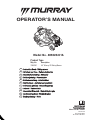 1
1
-
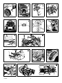 2
2
-
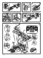 3
3
-
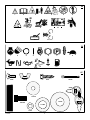 4
4
-
 5
5
-
 6
6
-
 7
7
-
 8
8
-
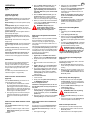 9
9
-
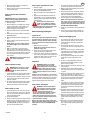 10
10
-
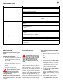 11
11
-
 12
12
-
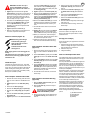 13
13
-
 14
14
-
 15
15
-
 16
16
-
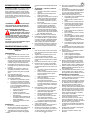 17
17
-
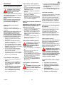 18
18
-
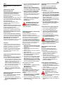 19
19
-
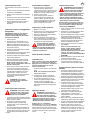 20
20
-
 21
21
-
 22
22
-
 23
23
-
 24
24
-
 25
25
-
 26
26
-
 27
27
-
 28
28
-
 29
29
-
 30
30
-
 31
31
-
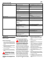 32
32
-
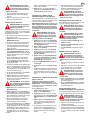 33
33
-
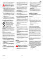 34
34
-
 35
35
-
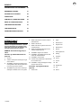 36
36
-
 37
37
-
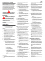 38
38
-
 39
39
-
 40
40
-
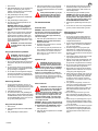 41
41
-
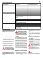 42
42
-
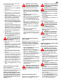 43
43
-
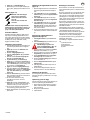 44
44
-
 45
45
-
 46
46
-
 47
47
-
 48
48
-
 49
49
-
 50
50
-
 51
51
-
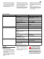 52
52
-
 53
53
-
 54
54
-
 55
55
-
 56
56
-
 57
57
-
 58
58
-
 59
59
-
 60
60
-
 61
61
-
 62
62
-
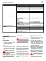 63
63
-
 64
64
-
 65
65
-
 66
66
-
 67
67
-
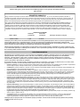 68
68
-
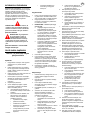 69
69
-
 70
70
-
 71
71
-
 72
72
-
 73
73
-
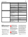 74
74
-
 75
75
-
 76
76
-
 77
77
-
 78
78
-
 79
79
-
 80
80
-
 81
81
-
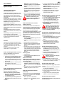 82
82
-
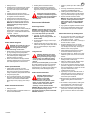 83
83
-
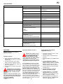 84
84
-
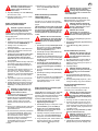 85
85
-
 86
86
-
 87
87
-
 88
88
-
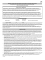 89
89
-
 90
90
-
 91
91
-
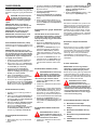 92
92
-
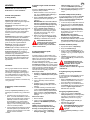 93
93
-
 94
94
-
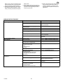 95
95
-
 96
96
-
 97
97
-
 98
98
-
 99
99
-
 100
100
-
 101
101
-
 102
102
-
 103
103
-
 104
104
-
 105
105
-
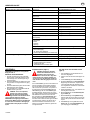 106
106
-
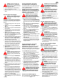 107
107
-
 108
108
-
 109
109
-
 110
110
-
 111
111
-
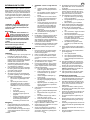 112
112
-
 113
113
-
 114
114
-
 115
115
-
 116
116
-
 117
117
-
 118
118
-
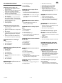 119
119
-
 120
120
-
 121
121
-
 122
122


Murray Lawn Mower 405628x51A Kasutusjuhend
- Tüüp
- Kasutusjuhend
teistes keeltes
Muud dokumendid
-
Ryobi RLM1956MEB Kasutusjuhend
-
Simplicity 884065 Kasutusjuhend
-
-
-
-
-
Jacobsen Super LF 1880 68007 Omaniku manuaal
-
Ransomes 62304, 62379 Omaniku manuaal
-
-
McCulloch BA165H107RB Kasutusjuhend