Milwaukee M12 3PL Kasutusjuhend

Tüüp
Kasutusjuhend
GB
Original instructions 2
D
Originalbetriebsanleitung 14
F
Notice originale 26
I
Istruzioni originali 38
E
Manual original 50
P
Manual original 62
NL
Oorspronkelijke gebruiksaanwijzing 74
DK
Original brugsanvisning 86
N
Original bruksanvisning 98
S
Bruksanvisning i original 110
FIN
Alkuperäiset ohjeet 122
GR
   134
TR
Orijinal iletme talimatı146
CZ
Pvodním návodem k používání 158
SK
Pôvodný návod na použitie 170
PL
Instrukcj oryginaln182
HU
Eredeti használati utasítás 194
SLO
Izvirna navodila 206
HR
Originalne pogonske upute 218
LV
Instrukcijm oriinlvalod230
LT
Originali instrukcija 242
EST
Algupärane kasutusjuhend 254
RUS
    266
BG
    278
RO
Instruciuni de folosire originale 290
MK
   302
UKR
  
314
AR
 
337
M12 3PL
2ENGLISH
WARNING:
Avoid direct eye exposure. The laser beam can cause severe eye damage and/or blindness.
Do not stare into the laser beam or direct it towards other people unnecessarily.
Caution! The laser emitting product may be behind you in some applications. Be careful when
facing the product.
Warning:
Do not operate the laser around children or allow children to operate the laser.
The re ective surface could re ect the beam back at the operator or other persons.
Warning: Use of controls, adjustments, or the performance of procedures other than those
speci ed in the manual may result in hazardous radiation exposure.
When the laser is brought into a warm environment from very cold conditions, or vice versa,
allow it to come to the surrounding temperature before use.
Always store the laser indoors, avoid substantial knocks, continuous vibration or extreme
temperatures.
Always keep the tool away from dust, liquids and high humidity. These may damage internal
components or a ect accuracy.
If laser radiation hits your eye, you must close your eyes and immediately turn your head away
from the beam.
Do not position the laser beam so that it unintentionally blinds you or others.
Do not look into a laser beam using magnifying optical devices such as binoculars or a
telescope, as this will increase the level of eye injury.
If you use laser goggles to enhance the visibility of the laser beam, please notice that they will
not protect your eyes against laser radiation.
Do not remove or deface warning labels on the laser level.
Do not disassemble the laser level, laser radiation can cause serious eye injury.
When not in use, turn o the power, engage the pendulum lock and place the laser in its
carrying pouch.
Make sure the pendulum lock mechanism is engaged before transporting the laser.
Note: If the pendulum lock mechanism is not engaged before transportation, internal
mechanical damage may occur.
Do not use aggressive cleaning agents or solutions. Use only a clean, soft cloth for cleaning.
Avoid heavy impact to or dropping of the laser. The accuracy of the laser should be checked
before use if it has been dropped or subjected to other mechanical stresses.
Any repair required on this laser product should be performed only by authorised service
personnel.
Do not operate the product in explosion hazardous areas or in aggressive environments.
If the laser level is not in use for a long period of time, remove the batteries from the battery
compartment. This will prevent batteries from leaking and corrosion damage.
Flat batteries must not be disposed of with household waste. Care for the environment
and take them to the collection points provided in accordance with national or local
regulations. The laser must not be disposed with household waste. Dispose of the
product appropriately in accordance with the national regulations in force in your country.
Adhere to the national and country speci c regulations. Please contact your local authority or
your dealer for how to dispose of batteries properly.
European Conformity Mark
British Conformity Mark
I
mportant safety instructions .......................................................................................................2
Maintenance ...............................................................................................................................3
Technical data.............................................................................................................................3
Speci c conditions of use ...........................................................................................................3
Overview.....................................................................................................................................4
Accessory ...................................................................................................................................5
Replace batteries........................................................................................................................5
Fuel gauge..................................................................................................................................6
Low battery indication .................................................................................................................6
Track clip ....................................................................................................................................6
Wall mount & green target plate .................................................................................................7
Working in self-leveling mode .....................................................................................................8
Working in manual mode ............................................................................................................9
Detector ....................................................................................................................................10
Accuracy check ........................................................................................................................10
CONTENTS
I
MPORTANT SAFETY INSTRUCTIONS
CAUTION! WARNING! DANGER!
Do not use the product before you have studied the safety instructions and the user manual.
Laser Classi cation
Laser Beam
outlet aperture
WARNING:
It is a Class 2 laser product in accordance
with EN60825-1:2014 .
LASER
2
3ENGLISH
MAINTENANCE
Wipe the aperture lens and the body of the laser with a clean soft cloth. Do not use solvents.
Although the laser is dust and dirt resistant to a certain degree, do not store in dusty places as
long term exposure may damage internal moving parts.
If the laser is exposed to water, dry the laser level before returning it to the carrying case to
prevent corrosion damage.
TECHNICAL DATA
Laser Class 2
Self-Leveling Range ± 4°
Self-Leveling Time 3 s
Battery technology Li-Ion
Voltage DC 12 V
Protection class (water and dust
protection) IP54*
Max. altitude 2000 m
Relativ air humidity max. 80%
Pollution degree according to
IEC 61010-1 2**
Pulse duration tP 80 s
Functions 3 planes (1 horizontal, 2 vertical)
Frequency 10 kHz
Projections 3 x 360° lines green ( 1x horizontal, 2x vertical)
Diode Quantity 3
Diode type 50 mW
Operating time 15 hrs with M12 4.0 Ah Battery
Tripod mount 1/4" / 5/8" thread
Suitable detector Milwaukee LLD50
Laser Line Width < 9.53mm @ 30m
Wavelength 510 - 530 nm Laser Class II
Max. Power 8 mW
Accuracy +/- 3 mm / 10 m
Fan angle 360°
Colour green
Working Range 38 m (with detector 50 m)
Recommended ambient operating
temperature -10°C - +40 °C
Storage Temperature -20°C - +50 °C
Recommended battery types M12 B...
Dimensions 193 mm x 110 mm x 168 mm
Weight (incl. Battery 6 Ah) 1607 g
* The Lithium-ion battery and the battery compartment are excluded from IP 54.
** Only non-conductive deposits occur, wherby occasional temporary conductivity caused by
condensation is expected.
SPECIFIC CONDITIONS OF USE
The product is designed for mainly indoor use. For outdoor use make sure that the boundary
conditions are the same as for indoor use.
The laser is innovatively designed for a very broad range of professional jobs, including:
- Aligning tiles, marble, cabinets, borders, moldings and trimmings
- Marking layout for doors, windows, rails, stairs, fences, gates, decks and pergolas installation.
- Transferring reference point for light installations, vents, transfer of heights, levelling perimeter
walls, wall studs, setting out tracks on oors and all other professional use.
- It is intended for determining and checking horizontal and vertical lines.
Do not use this product in any other way as stated for normal use.
4ENGLISH
OVERVIEW
Power on indicator
Mode button
Short press:
turn ON/OFF the corresponding planes:
horizontal plane
Long press:
switch normal mode / power save mode
10° pivot micro adjustment (+/-5° from center)
Horizontal laser plane
Vertical laser plane front
5/8" tripod mount
M12 Battery
Rotation dial
O / locked
On / manual mode
On / self leveling mode
Magnetic mount
LED indicator fuel gauge
Vertical laser plane side
vertical plane front
vertical plane side
1/4" tripod mount
Track clip
5
click
ENGLISH
ACCESSORY
Accessory - Not included in standard equipment, available as an accessory.
Clamp LM360
Detector LLD50
REPLACE BATTERIES
Only use Milwaukee M12 rechargeable batteries.
Tripod TRP180
6ENGLISH
LOW BATTERY INDICATION
When the voltage is low, the laser switch to power safe mode.
The laser will blink in self leveling mode
4 sec. 1 sec.
The laser will blink in manual mode
8 sec. 1 sec.
From now on it is still possible to continue the work.
When the voltage is too low, the laser and the LED will ash 4 times and it automatically shuts
down.
After switch on the laser the fuel gauge will display the battery life
FUEL GAUGE TRACK CLIP
Fix the track clip with screws to a pillar.
66-100%
45-65%
18-44%
8-17%
<7%
0%
> 40°C
4x
4x
4x
Or clamp the track clip to ceiling channels,
racks....
1
2
3
7ENGLISH
WALL MOUNT & GREEN TARGET PLATE Use the green target plate to improve visibility of the laser beam in unfavourable conditions
and at greater distances.
Tripod mount 1/4"
Tripod mount 5/8"
Use the magnetic wall mount to x the laser
to a wall or metallic structures or similar. Or x it with a screw or nail on a pillar
Turn the laser 330°. Use the tripod mount to x the laser on a tripod Use the adjustment knob for 10° pivot micro
adjustment
8
1
3
2
4
5
6
ENGLISH
WORKING IN SELF-LEVELING MODE
In self-leveling mode the laser will level itself in a ± 4° range and can project a horizontal
plane and two vertical planes.
Place the laser on a solid at
vibration free surface or on a
tripod.
Turn the rotation dial to: .
Laser mode indicator LED will display
Horizontal laser will be emitted.
The laser will generate 3 laser
planes.
(A) horizontal laser plane
(B) vertival laser plane side
(C) vertical laser plane front
(D) The laser will generate cross
planes when all planes are
activated.
Choose the planes
that you want to
work with by
pushing buttons.
If the initial level of the
laser is beyond ±4° and
the self-leveling mode is
activated, the laser
beams will ash
.
In this case reposition the
laser.
Before moving the laser, turn the
rotation dial to: .
This will lock the pendulum and
protect your laser.
1/4" male thread
5/8" male thread
> 4°
> 4°
A
D
D
D
C
B
9
1
2
3
4
5
6
ENGLISH
WORKING IN MANUAL MODE
In manual mode the lasers self-leveling mechanism is disabled and the laser lines can be set
at any slope required.
Place the laser on a solid at
vibration free surface or on a
tripod.
Turn the rotation dial to:
Laser mode indicator LED will display
Horizontal laser will be emitted.
Same as in the self-leveling
mode, the laser will generate
3 laser planes, but the laser
beams are interrupted every 8
seconds.
8 sec. 8 sec. 8 sec.
Choose the
beams that you
want to work with
by pushing the
buttons.
Tilt the laser and adjust to the
desired angle and height.
To turn the Manual mode o ,
turn the rotation dial to: .
or
turn the rotation dial to: .
10ENGLISH
DETECTOR
For outdoor work under direct sunlight, or bright conditions and for extended indoor ranges of
up to 50 meters / 164 feet, use the Milwaukee detector.
A detector is not included and must be purchased separately.
For information on how to operate the detector, please refer to the operating instructions for
the detector.
ACCURACY CHECK
This laser left the factory fully calibrated. Milwaukee recommends the user to check the
accuracy of the laser periodically, especially if the unit falls or is mishandled.
If the maximum deviation of the laser is exceeded in one of the accuracy checks,please
contact one of our Milwaukee service agents (see our list of guarantee/service addresses).
1. Checking the height accuracy of the horizontal plane.
2. Checking the leveling accuracy of the horizontal plane.
3. Checking the leveling accuracy of the vertical plane.
Before checking the laser accuracy, after mounting the laser on the tripod, check the leveling
of the tripod.
11
1
1. Set up the laser on a tripod or on a at surface
between two walls A and B, approximately 5 meters apart.
2. Position the laser level approximately 0.5 meter from wall A.
3. Switch ON the self-leveling mode and press the button to project the horizontal and the
vertical planes towards wall A.
4. Mark the center of the cross planes on the wall as a1.
a1
§P
P
AB
Turn the laser 180° towards wall B and mark the center of the cross planes as b1 on the
wall.
180°
a1 b1
5. Move the laser level towards wall B and position it approximately 0.5 meter from wall B.
6. Mark on wall B the center of the cross planes as b2.
A
a1 b2
P
b1
B
7. Turn the laser 180° towards wall A, and mark on the wall the center of the cross planes
as a2.
A
a2
a1
180° B
b2
b1
8. Measure the distances:
a= |a2-a1|
b= |b1-b2|
9. The di erence | a – b| should be no more than 2 mm.
ENGLISH
CHECKING THE HEIGHT ACCURACY OF THE HORIZONTAL PLANE (UP AND DOWN DEVIATION)
12
2
For this check, a free surface of approx. 5 x 5 meters is required.
1. Set up the laser on a tripod or on a solid surface between two walls A and B, approximately
5 meters apart.
2. Position the laser level approximately 2.5 meters from the center of the room.
3. Switch ON the self-leveling mode and press the button to project the horizontal line towards
wall A and B.
4. Mark the center of the laser line point a1 on wall A and point b1 on wall B.
A
B
a1
b1
5. Move the laser level approximately 5 meters away and turn the laser 180° towards wall A
and B.
6. Mark the center of the laser line point a2 on wall A and point b2 on wall B.
A
B
a2
a1
b2
b1
7. Measure the distances:
a= |a2- a1|
b= |b1- b2|
8. The di erence | a – b| should be no more than 2 mm.
ENGLISH
CHECKING THE LEVEL ACCURACY OF THE HORIZONTAL PLANES (SIDE TO SIDE INCLINATION)
13
3
1. Hang an approximately 4 m plumb
line on a wall.
2. After the plumb line has settled, mark
point a1 on the wall, behind the
plumb line, near the plumb cone.
a1
P
a1
a2
3. Set up the laser on a tripod or on a
at surface in front of the wall at a
distance of approximately 2 m.
4. Switch ON the self-leveling mode,
and press the button to project the
vertical beam towards the plumb line.
5. Turn the laser so that the vertical
plane will merge with the plumb line
below the hanging point.
6. Mark point a2 on the wall, in the
middle of the vertical plane at the
same height as a1.
7. The distance between a1 and a2,
should be no more than 1 mm.
ENGLISH
CHECKING THE LEVEL ACCURACY OF THE VERTICAL
PLANE
14DEUTSCH
Warnung:
Die Augen nicht direkt dem Laserstrahl aussetzen. Der Laserstrahl kann schwerwiegende Augenschäden
und/oder Erblinden verursachen.
Nicht direkt in den Laserstrahl blicken und den Strahl nicht unnötigerweise auf andere Personen richten.
Vorsicht! Bei einigen Anwendungen kann sich das laseremittierende Gerät hinter Ihnen be nden.
Wenden Sie sich in diesem Fall vorsichtig um.
Betreiben Sie den Laser nicht in Gegenwart von Kindern und erlauben Sie ihnen auf keinen Fall, den
Laser zu benutzen.
Achtung! Eine re ektierende Ober äche kann den Laserstrahl zurück an den Bediener oder andere
Personen re ektieren.
Warnung: Die Verwendung von Steuerelementen, Einstellungen oder die Durchführung von anderen als
den im Handbuch festgelegten Verfahren kann zu gefährlicher Strahlenbelastung führen.
Wird der Laser von einer sehr kalten in eine warme Umgebung (oder umgekehrt) gebracht, muss es vor
Gebrauch die Umgebungstemperatur erreichen.
Den Laser nicht im Freien aufbewahren und vor Schlägen, dauerhaften Vibrationen und extremen
Temperaturen schützen.
Den Laser vor Staub, Nässe und hoher Luftfeuchtigkeit schützen. Andernfalls können innere Bauteile
beschädigt oder die Genauigkeit beein usst werden.
Falls Laserstrahlung ins Auge tri t, die Augen schließen und den Kopf sofort aus dem Strahl wegdrehen.
Achten Sie darauf, den Laserstrahl so zu positionieren, dass Sie selbst oder andere Personen davon
nicht geblendet werden.
Nicht mit optischen Vergrößerungsgeräten, wie Ferngläsern oder Teleskopen, in den Laserstrahl blicken.
Andernfalls erhöht sich die Gefahr von schwerwiegenden Augenschäden.
Beachten Sie, dass Lasersichtbrillen zum besseren Erkennen der Laserlinien dienen, die Augen jedoch
nicht vor Laserstrahlung schützen.
Warnschilder auf dem Lasergerät dürfen nicht entfernt oder unkenntlich gemacht werden.
Den Laser nicht auseinanderbauen. Laserstrahlung kann schwere Augenverletzungen verursachen.
Vor dem Transport des Lasers sicherstellen, dass die Pendelarretierung eingerastet ist.
Hinweis: Bei nicht eingerasteter Pendelarretierung kann es während des Transports zu Beschädigungen
im Inneren des Geräts kommen.
Keine aggressiven Reinigungsmittel oder Lösungsmittel verwenden. Nur mit einem sauberen, weichen
Tuch reinigen.
Den Laser vor heftigen Stößen und Stürzen schützen. Nach einem Sturz oder starken mechanischen
Einwirkungen ist die Genauigkeit des Geräts vor Gebrauch zu überprüfen.
Erforderliche Reparaturen an diesem Lasergerät dürfen nur von autorisiertem Fachpersonal durchgeführt
werden.
Das Produkt darf nicht in einer explosionsgefährdeten oder aggressiven Umgebung eingesetzt werden.
Vor längerem Nichtgebrauch des Geräts die Batterien aus dem Batteriefach entnehmen. So lassen sich
das Auslaufen der Batterien und damit verbundene Korrosionsschäden vermeiden.
Leere Batterien dürfen nicht über den Hausmüll entsorgt werden. Gebrauchte Batterien zur
umweltgerechten Entsorgung gemäß nationaler oder lokaler Vorschriften an den dafür
vorgesehenen Sammelstellen abgeben. Das Gerät darf nicht im Hausmüll entsorgt werden. Gerät
sachgemäß entsorgen. Länderspezi sche Entsorgungsvorschriften befolgen. Wenden Sie sich
an die örtliche Behörde oder Ihren Händler, um Auskunft über die Entsorgung zu erhalten.
Europäisches Konformitätszeichen
Britisches Konformitätszeichen
Wichtige Sicherheitshinweise ...................................................................................................14
Wartung ....................................................................................................................................15
Technische Daten .....................................................................................................................15
Bestimmungsgemäße Verwendung..........................................................................................15
Übersicht ..................................................................................................................................16
Zubehör ...................................................................................................................................17
Akku wechseln .........................................................................................................................17
Akkukapazitätsanzeige ............................................................................................................18
Anzeige für niedrigen Akkukapazität .......................................................................................18
Deckenbefestigung ..................................................................................................................18
Wandhalterung und grüne Zielplatte ........................................................................................19
Arbeiten im Selbstnivelliermodus .............................................................................................20
Arbeiten im manuellen Modus ..................................................................................................21
Detektor ....................................................................................................................................22
Genauigkeit überprüfen ............................................................................................................22
INHALT
WICHTIGE SICHERHEITSHINWEISE
ACHTUNG! WARNUNG! GEFAHR!
Nehmen Sie das Produkt erst in Gebrauch, wenn Sie die Sicherheitshinweise und die
Gebrauchsanweisung gelesen haben.
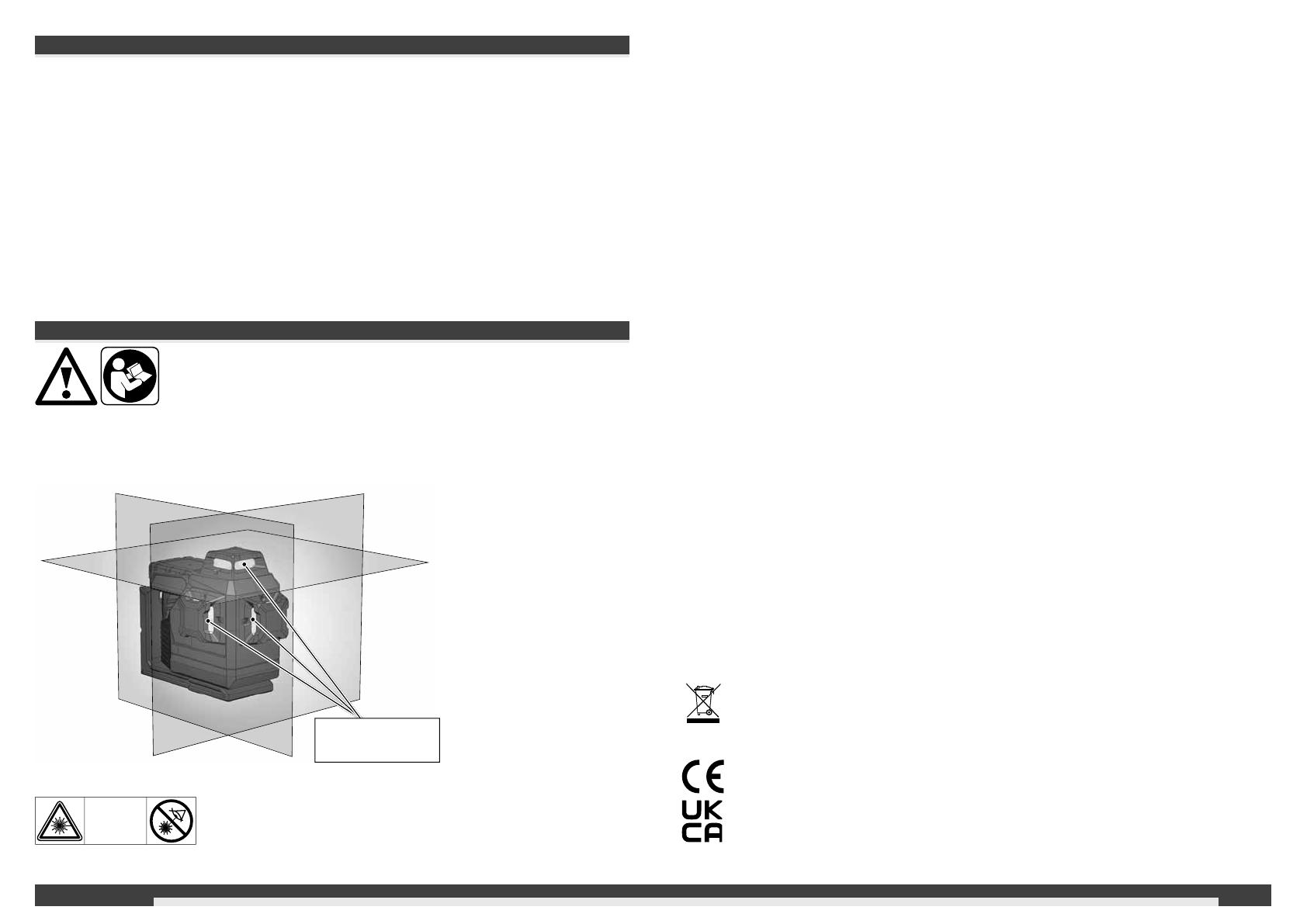
Laserklassi zierung
Laserstrahl-
austrittsö nung
WARNUNG:
Das Produkt entspricht der Laserklasse 2 gemäß EN60825-1:2014 .
LASER
2
15DEUTSCH
WARTUNG
Das Objektiv und das Gehäuse des Lasers mit einem weichen, sauberen Tuch reinigen. Keine
Lösungsmittel verwenden.
Auch wenn das Gerät bis zu einem gewissen Grad staub- und schmutzbeständig ist, sollte es
nicht längerfristig an einem staubigen Ort aufbewahrt werden, da andernfalls innenliegende
bewegliche Teile beschädigt werden können.
Sollte der Laser nass werden, ist es vor dem Einsetzen in den Trageko er zu trocknen, damit
keine Rostschäden entstehen.
TECHNISCHE DATEN
Laserklasse 2
Selbstnivellierungsbereich ± 4°
Selbstnivellierungsdauer 3 s
Batterietyp Li-Ion
Spannung DC 12V
Schutzart (Spritzwasser und Staub) IP54*
Max. Höhenlage 2000 m
Relative Luftfeuchtigkeit max. 80%
Verschmutzungsgrad nach
IEC 61010-1 2**
Pulsdauer tP 80 s
Funktionen 3 Ebenen (1 horizontale Linie, 2 vertikale Linien)
Frequenz 10 kHz
Projektionen 3 x 360° Linien grün (1x horizontal, 2x vertikal)
Anzahl Dioden 3
Diodentyp 50 mW
Betriebszeit 15 Stunden mit Akku M12 4.0 Ah
Stativgewinde 1/4“ / 5/8“
Geeigneter Detektor Milwaukee LLD50
Laserlinie Breite < 9,53mm @ 30m
Wellenlänge 510 - 530 nm Laserklasse II
Maximale Leistung 8 mW
Genauigkeit +/- 3 mm / 10 m
Ö nungswinkel 360°
Farbe grün
Reichweite 38 m (mit Detektor 50 m)
Empfohlene Betriebstemperatur -10 °C bis +40 °C
Lagertemperatur -20 °C bis +50 °C
Empfohlene Akkutypen M12 B...
Abmessungen 193 mm x 110 mm x 168 mm
Gewicht (inkl. Batterien 6 Ah) 1607 g
* Der Lithium-ion Akku und das Akkufach sind von IP54 ausgeschlossen.
** Es tritt nur eine nicht leitfähige Verschmutzung auf, wobei jedoch gelegentlich eine
vorübergehende durch Betauung verursachte Leitfähigkeit erwartet wird.
BESTIMMUNGSGEMÄSSE VERWENDUNG
"Das Produkt ist vorzugsweise für den Einsatz in Innenräumen bestimmt. Bei Einsatz im Freien
ist darauf zu achten, dass die Rahmenbedingungen denen im
Innenraum entsprechen."
Dieser innovative Laser ist für einen breiten professionellen Anwendungsbereich ausgelegt, wie
z. B.:
- Ausrichten von Fliesen, Marmorplatten, Schränken, Bordüren, Formteilen und Besätzen
- Markieren der Grundlinien für den Einbau von Türen, Fenstern, Schienen, Treppen, Zäunen,
Toren, Veranden und Pergolen.
- Für die Bestimmung und Prüfung von horizontalen und vertikalen Linien.
- Nivellieren von abgehängten Decken und Rohrleitungen, Fensteraufteilung und
Rohrausrichtung, Nivellieren von Umfassungswänden für Elektroinstallationen
Dieses Produkt darf nur wie angegeben bestimmungsgemäß verwendet werden.
16DEUTSCH
ÜBERSICHT
Einschaltanzeige
Modustaste
Kurzes Drücken: die entsprechenden Ebenen EIN/
AUS schalten
- horizontale Linie
Langes Drücken: Umschalten Normalmodus /
Energiesparmodus
10 ° Feineinstellung (+/-5° von der Mitte)
Horizontale Laserlinie
Vertikale Laserlinie vorn
Stativhalterung 5/8“
M12 Akku
Drehknopf
Aus / gesperrt
Ein / manueller Modus
Ein / Selbstnivellierungsmodus
Magnethalterung
LED-Anzeige Akkukapazität
Vertikale Laserlinie seitlich
- vertikale Linie vorn
- vertikale Linie seitlich
Stativhalterung 1/4“
Deckenbefestigung
17
click
DEUTSCH
ZUBEHÖR
Zubehör - Nicht in der Standardausstattung enthalten, als Zubehör erhältlich.
Klemme LM360
Detektor LLD50
AKKU WECHSELN
Verwenden Sie nur einen wiederau adbaren Milwaukee-Akku vom Typ M12.
Stativ TRP180
18DEUTSCH
ANZEIGE FÜR NIEDRIGEN AKKUKAPAZITÄT
Wenn die Spannung niedrig ist, schaltet der Laser in den Energiesparmodus.
Der Laser blinkt im Selbstnivellierungsmodus
4 Sek. 1 Sek.
Der Laser blinkt im manuellen Modus
8 Sek. 1 Sek.
Von nun an ist es weiterhin möglich, die Arbeit fortzusetzen.
Wenn die Spannung zu niedrig ist, blinken der Laser und die LED 4x und schalten sich
automatisch aus.
Nach dem Ein- oder Ausschalten des Lasers zeigt die Akkukapazitätsanzeige die
Akkukapazität an
AKKUKAPAZITÄTSANZEIGE DECKENBEFESTIGUNG
Befestigen Sie die Deckenbefestigung mit
Schrauben an einer Säule.
66-100%
45-65%
18-44%
8-17%
<7%
0%
> 40°C
4x
4x
4x
Verwenden Sie die Deckenbefestigung, um
den Laser an Deckenkanälen, Racks…
festzuklemmen.
1
2
3
19DEUTSCH
WANDHALTERUNG UND GRÜNE ZIELPLATTE Verwenden Sie die grüne Zielplatte, um die Sichtbarkeit des Laserstrahls unter ungünstigen
Bedingungen und in größeren Entfernungen zu verbessern.
Stativgewinde 5/8“
Stativgewinde 1/4“
Mit der magnetischen Wandhalterung lässt
sich der Laser an Wänden, Metallstrukturen
o. ä. befestigen.
Oder mit einer Schraube oder Nagel an einem
Pfosten befestigen
Drehen Sie den Laser um 360 °. Befestigen Sie den Laser mit der Stativaufnahme auf einem Stativ. Verwenden Sie den Einstellknopf für die 10°
Pivot-Feineinstellung
20
1
3
2
4
5
6
DEUTSCH
ARBEITEN IM SELBSTNIVELLIERMODUS
Im Selbstnivelliermodus richtet sich der Laser selbst in einem Bereich von ±4° aus. Dazu
werden eine horizontale Linie,und zwei vertikale Linien projiziert.
Den Laser auf einen festen,
ebenen und vibrationsfreien
Untergrund stellen oder auf
einem Stativ montieren.
Drehen Sie den Drehknopf auf: .
Die LED für die Lasermodusanzeige leuchtet
Der horizontaler Laser ist aktiviert.
Der Laser erzeugt 3 Laserlinien.
(A) Horizontale Linie nach vorne
(B) Vertikale Linie zur Seite
(C) Vertikale Linie nach vorn
(D) Wenn alle Linien aktiviert
sind, erzeugt der Laser
Kreuzlinien.
Die gewünschten
Linien über die
Tasten auswählen.
Wenn der Laser bei
aktivierter
Selbstnivellierung
anfangs nicht auf ±4°
ausgerichtet ist, blinken
die Laserlinien.
.
In diesem Fall den Laser
neu positionieren.
Vor dem Umsetzen des Lasers den
Drehknopf auf stellen.
Dadurch wird das Pendel arretiert und
der Laser geschützt.
1/4“ Gewindebolzen
5/8“ Gewindebolzen
> 4°
> 4°
A
D
D
D
C
B
  • Page 1 1
  • Page 2 2
  • Page 3 3
  • Page 4 4
  • Page 5 5
  • Page 6 6
  • Page 7 7
  • Page 8 8
  • Page 9 9
  • Page 10 10
  • Page 11 11
  • Page 12 12
  • Page 13 13
  • Page 14 14
  • Page 15 15
  • Page 16 16
  • Page 17 17
  • Page 18 18
  • Page 19 19
  • Page 20 20
  • Page 21 21
  • Page 22 22
  • Page 23 23
  • Page 24 24
  • Page 25 25
  • Page 26 26
  • Page 27 27
  • Page 28 28
  • Page 29 29
  • Page 30 30
  • Page 31 31
  • Page 32 32
  • Page 33 33
  • Page 34 34
  • Page 35 35
  • Page 36 36
  • Page 37 37
  • Page 38 38
  • Page 39 39
  • Page 40 40
  • Page 41 41
  • Page 42 42
  • Page 43 43
  • Page 44 44
  • Page 45 45
  • Page 46 46
  • Page 47 47
  • Page 48 48
  • Page 49 49
  • Page 50 50
  • Page 51 51
  • Page 52 52
  • Page 53 53
  • Page 54 54
  • Page 55 55
  • Page 56 56
  • Page 57 57
  • Page 58 58
  • Page 59 59
  • Page 60 60
  • Page 61 61
  • Page 62 62
  • Page 63 63
  • Page 64 64
  • Page 65 65
  • Page 66 66
  • Page 67 67
  • Page 68 68
  • Page 69 69
  • Page 70 70
  • Page 71 71
  • Page 72 72
  • Page 73 73
  • Page 74 74
  • Page 75 75
  • Page 76 76
  • Page 77 77
  • Page 78 78
  • Page 79 79
  • Page 80 80
  • Page 81 81
  • Page 82 82
  • Page 83 83
  • Page 84 84
  • Page 85 85
  • Page 86 86
  • Page 87 87
  • Page 88 88
  • Page 89 89
  • Page 90 90
  • Page 91 91
  • Page 92 92
  • Page 93 93
  • Page 94 94
  • Page 95 95
  • Page 96 96
  • Page 97 97
  • Page 98 98
  • Page 99 99
  • Page 100 100
  • Page 101 101
  • Page 102 102
  • Page 103 103
  • Page 104 104
  • Page 105 105
  • Page 106 106
  • Page 107 107
  • Page 108 108
  • Page 109 109
  • Page 110 110
  • Page 111 111
  • Page 112 112
  • Page 113 113
  • Page 114 114
  • Page 115 115
  • Page 116 116
  • Page 117 117
  • Page 118 118
  • Page 119 119
  • Page 120 120
  • Page 121 121
  • Page 122 122
  • Page 123 123
  • Page 124 124
  • Page 125 125
  • Page 126 126
  • Page 127 127
  • Page 128 128
  • Page 129 129
  • Page 130 130
  • Page 131 131
  • Page 132 132
  • Page 133 133
  • Page 134 134
  • Page 135 135
  • Page 136 136
  • Page 137 137
  • Page 138 138
  • Page 139 139
  • Page 140 140
  • Page 141 141
  • Page 142 142
  • Page 143 143
  • Page 144 144
  • Page 145 145
  • Page 146 146
  • Page 147 147
  • Page 148 148
  • Page 149 149
  • Page 150 150
  • Page 151 151
  • Page 152 152
  • Page 153 153
  • Page 154 154
  • Page 155 155
  • Page 156 156
  • Page 157 157
  • Page 158 158
  • Page 159 159
  • Page 160 160
  • Page 161 161
  • Page 162 162
  • Page 163 163
  • Page 164 164
  • Page 165 165
  • Page 166 166
  • Page 167 167
  • Page 168 168
  • Page 169 169
  • Page 170 170
  • Page 171 171
  • Page 172 172
  • Page 173 173
  • Page 174 174
  • Page 175 175
  • Page 176 176
  • Page 177 177
  • Page 178 178
  • Page 179 179
  • Page 180 180
  • Page 181 181
  • Page 182 182
  • Page 183 183
  • Page 184 184
  • Page 185 185
  • Page 186 186
  • Page 187 187
  • Page 188 188
  • Page 189 189
  • Page 190 190
  • Page 191 191
  • Page 192 192
  • Page 193 193
  • Page 194 194
  • Page 195 195
  • Page 196 196
  • Page 197 197
  • Page 198 198
  • Page 199 199
  • Page 200 200
  • Page 201 201
  • Page 202 202
  • Page 203 203
  • Page 204 204
  • Page 205 205
  • Page 206 206
  • Page 207 207
  • Page 208 208
  • Page 209 209
  • Page 210 210
  • Page 211 211
  • Page 212 212
  • Page 213 213
  • Page 214 214
  • Page 215 215
  • Page 216 216
  • Page 217 217
  • Page 218 218
  • Page 219 219
  • Page 220 220
  • Page 221 221
  • Page 222 222
  • Page 223 223
  • Page 224 224
  • Page 225 225
  • Page 226 226
  • Page 227 227
  • Page 228 228
  • Page 229 229
  • Page 230 230
  • Page 231 231
  • Page 232 232
  • Page 233 233
  • Page 234 234
  • Page 235 235
  • Page 236 236
  • Page 237 237
  • Page 238 238
  • Page 239 239
  • Page 240 240
  • Page 241 241
  • Page 242 242
  • Page 243 243
  • Page 244 244
  • Page 245 245
  • Page 246 246
  • Page 247 247
  • Page 248 248
  • Page 249 249
  • Page 250 250
  • Page 251 251
  • Page 252 252
  • Page 253 253
  • Page 254 254
  • Page 255 255
  • Page 256 256
  • Page 257 257
  • Page 258 258
  • Page 259 259
  • Page 260 260
  • Page 261 261
  • Page 262 262
  • Page 263 263
  • Page 264 264
  • Page 265 265
  • Page 266 266
  • Page 267 267
  • Page 268 268
  • Page 269 269
  • Page 270 270
  • Page 271 271
  • Page 272 272
  • Page 273 273
  • Page 274 274
  • Page 275 275
  • Page 276 276
  • Page 277 277
  • Page 278 278
  • Page 279 279
  • Page 280 280
  • Page 281 281
  • Page 282 282
  • Page 283 283
  • Page 284 284
  • Page 285 285
  • Page 286 286
  • Page 287 287
  • Page 288 288
  • Page 289 289
  • Page 290 290
  • Page 291 291
  • Page 292 292
  • Page 293 293
  • Page 294 294
  • Page 295 295
  • Page 296 296
  • Page 297 297
  • Page 298 298
  • Page 299 299
  • Page 300 300
  • Page 301 301
  • Page 302 302
  • Page 303 303
  • Page 304 304
  • Page 305 305
  • Page 306 306
  • Page 307 307
  • Page 308 308
  • Page 309 309
  • Page 310 310
  • Page 311 311
  • Page 312 312
  • Page 313 313
  • Page 314 314
  • Page 315 315
  • Page 316 316
  • Page 317 317
  • Page 318 318
  • Page 319 319
  • Page 320 320
  • Page 321 321
  • Page 322 322
  • Page 323 323
  • Page 324 324
  • Page 325 325
  • Page 326 326
  • Page 327 327
  • Page 328 328
  • Page 329 329
  • Page 330 330
  • Page 331 331
  • Page 332 332
  • Page 333 333
  • Page 334 334
  • Page 335 335
  • Page 336 336
  • Page 337 337
  • Page 338 338

Milwaukee M12 3PL Kasutusjuhend

Tüüp
Kasutusjuhend