9938 / 1927300 / 3
SuomiEnglishDeutschFrançais Nederlands Svenska
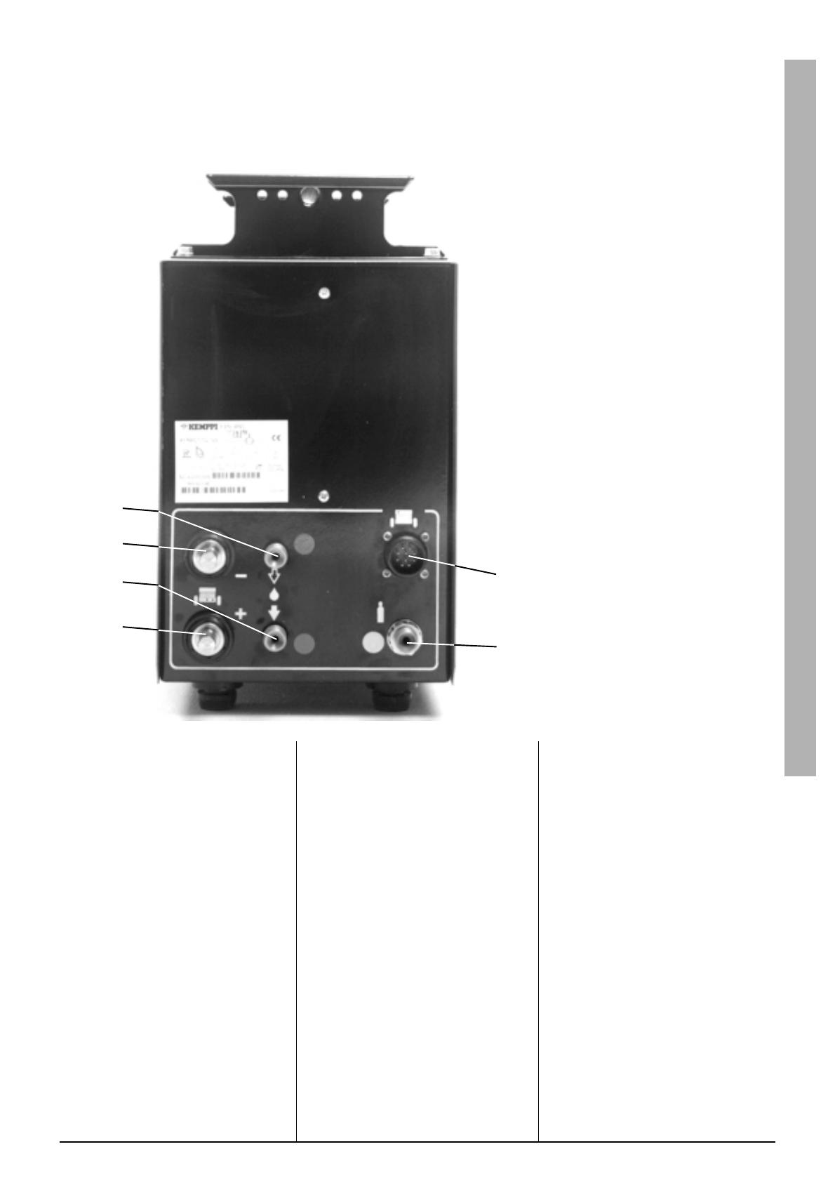
X8
d
X9
X2
c
b
X8 Hitsausjänniteliitäntä, + napa
Anslutning av svetskabel, pluspol
Welding voltage connection, positive
Schweißspannungsanschluß, Pluspol
Lasspanningsaansluiting, pluspool
Connecteur tension de soudage, positif
X9 Hitsausjänniteliitäntä, napa
Anslutning av svetskabel, minuspol
Welding voltage connection, negative
Schweißspannungsanschluß, Minuspol
Lasspanningsaansluiting, minpool
Connecteur tension de soudage, négatif
aJäähdytysnesteliitäntä, hitsauspoltin
Anslutning för kylvätska, svetsbrännare
Cooling liquid connection, welding
Anschluß für Kühlflüssigkeit, Schweiß-
brenner
Aansluiting voor koelvloeistof, lasbrander
Connecteur liquide refroidissement/
torche
bJäähdytysnesteliitäntä, syöttö
Anslutning för kylvätska, inmatning
Cooling liquid connection, supply
Anschluß für Kühlflüssigkeit, Einlauf
Aansluiting voor koelvloeistof, toevoer
Connecteur alimentation liquide de
refroidissement
4. Jäähdytysnesteletku, syöttö
Kylvätskeslang, inmatning
Cooling liquid hose, supply
Kühlflüssigkeitschlauch, einlauf
Vloeistofslang, toevoer
Alimentation liquide de refroidissement
5. Ohjauskaapeli
Manöverkabel
Control cable
Steuerkabel
Stuurkabel
Câble de commande
6. Ohjauskaapeli
Manöverkabel
Control cable
Steuerkabel
Stuurkabel
Câble de commande
7. Suojakaasuletku
Skyddsgasslang
Shielding gas hose
Schutzgasschlauch
Beschermgasslang
Tuyau gaz de protection
8. WU:n verkkoliitäntäjohto
Nätkabel för WU
Mains cable for WU
Netzkabel für WU
Netkabel voor WU
Câble dalimentation pour WU
9. TIG-poltin, kaasujäähdytteinen
TIG-brännare, gaskyld
TIG-torch, gas-cooled
WIG-Brenner, gasgekühlt
WIG-brander, gasgekoeld
Torche Tig, refroidie gaz
10. TIG-poltin, nestejäähdytteinen
TIG-brännare, vätskekyld
TIG-torch, liquid-cooled
WIG-Brenner, flüssikeitsgekühlt
WIG-brander, vloeistofgekoeld
Torche Tig, refroidie par liquide
11. Paluuvirtakaapeli
Återledare
Retur cable
Stromrückleitungskabel
Stroomterugvoerkabel
Câble de masse
12. Kaukosäätövälikaapeli
Mellankabel för fjärreglage
Interconnection cable for remote control
Zwischenkabel für Fernregelung
Tussenkabel voor afstandsbediening
Câble intermédiaire pour commande à
distance
13. Kaukosäätövälikaapeli
Mellankabel för fjärreglage
Interconnection cable for remote
control
Zwischenkabel für Fernregelung
Tussenkabel voor afstandsbediening
Câble intermédiaire pour commande à
distance
1-7. Toimitetaan välikaapelinippuna
Levereras som mellankabelbunt
Delivery as interconnection cable bundle
Lieferung als Zwischenkabelbündel
Levering als tussenkabelbundel
Livré en un faisceau
cJäähdytysnesteliitäntä, paluu
Anslutning för kylvätska, retur
Cooling liquid connection, return
Anschluß für Kühlflüssigkeit, Rücklauf
Aansluiting voor koelvloeistof, retour
Connecteur retour liquide de
refroidissement
dSuojakaasuliitäntä, syöttö
Anslutning för skyddsgas, inmatning
Connection for shielding gas, supply
Anschluss für Schutzgas, Einlauf
Aansluiting voor beschermgas, toevoer
Connecteur alimentation gaz de protection
1. Hitsausvirtakaapeli, + napa
Svetsströmkabel, pluspol
Welding current cable, positive
Schweißstromkabel, Pluspol
Lasstroomkabel, pluspool
Câble courant de soudage, positif
2. Hitsausvirtakaapeli, napa
Svetsströmkabel, minuspol
Welding current cable, negative
Schweißstromkabel, Minuspol
Lasstroomkabel, minpool
Câble courant de soudage, négatif
3. Jäähdytysnesteletku, paluu
Kylvätskeslang, retur
Cooling liquid hose, return
Kühlflüssigkeitschlauch, Rücklauf
Vloeistofslang, retour
Tuyau retour liquide de refroidissement


